Coinjection Mold Design

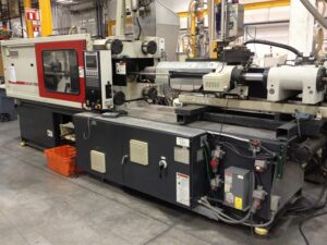
A schematic for a coinjection mold and feed framework is appeared in china injection molds factory. As appeared, material is conveyed to the form from the barrels of two infusion units 8 and 9 to the shape 10 through relating stream channels 15 and 16. These two channels merge at a control valve 17 before the sprue 11. The control valve utilizes a valve pin 18 with tW0 slanted stream channels. By pivoting the pin, one of the two stream diverts in the pin will enlist with the channels 15 or 16 to permit material to move from the comparing barrels 8 or 9 into the form while likewise forestalling the materials fr0m streaming between the barrels. A control framework is needed to Coordinate the activation of the valve pin 18 with the infusion of material from the barrels 8 and 9. Given this feed framework plan, a first and last infusion of the principal material is justified to maintain a strategic distance from pollution of any material living between the valve pin 18 and the sprue 11 as recently talked about regarding molds & tooling services china.

Generally, plan of coinjection molds is fundamentally the same as that of regular molds; numerous ordinary molds can be effectively utilized in a coinjection interaction since the systems for coinjection are for the most part coordinated with the embellishment machine and not simply the form. In any case, the shape originator ought to adjust the examinations for coinjection. As to shape filling, the form planner ought to guarantee that the form pit is intended to accomplish the ideal filling designs at sensible pressing factors. Logical arrangements and recreations have been produced for the coinjection of two materials with different viscosities into a form [4, 5]; be that as it may, in numerous coinjection applications, the shape will work effectively if the shape is intended to fill totally with just the more gooey material. Examination of cooling, shrinkage, and discharge ought to likewise be adjusted to think about the soften temperatures and warm properties of the two materials. Given the diverse design of the coinjected shaping, a sensible methodology is to determine a”metamaterial”that has material properties with respect to the layer thickness of the two constitutive materials.

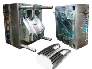
The mold utilizes a sliding fit along the vertical sides where the form center mates with the mold hole. While not examined in this reference, the sliding fit can be helped through the utilization control pins, interlocks, 0r keyways to mate the depression and center additions to maintain a strategic distance from sped up wear on the sliding surfaces.

Basic securing implies were additionally dissected including obstruction fits, attachment head cap screws, and dowels with freedom and impedance fits. The mold fashioner from china high precision mold manufacturer should make sure to give intends to attaching the hole and center additions to the remainder of the mold while giving tight control of area comparative with other form segments. Practically speaking, the arrangement of latches may meddle with different subsystems of the mold including part discharge and form cooling. In such cases, iterative update of the mold might be needed to proficiently find every one of the form’s subsystems without expanding the size and cost of the mold.

This article is from http://www.automoldchina.com/

Klarm Mold Offers Coinjection Molds

Co-injection molding is an interaction wherein two materials are consecutively infused into a mold cavity, commonly through a similar entryway in injection moulding service. Since the principal material structures a skin and the subsequent material structures the center of the molded part, it is feasible to utilize co-injection trim to deliver plastic parts with novel stylish or primary properties with possibly lower costs than infusion shaping. Some run of the mill co-injection molding applications include:

■The utilization of a first virgin material having favored restorative properties followed by a subsequent material having diverse underlying properties anC/or reused content, as in the belt of a vehicle guard.

The utilization of a first material followed by a second frothing material to create a restorative part with lower thickness, as in underlying froth applications.

■The utilization of a first material followed by a subsequent liquid, like air or water, to deliver an empty part like an entryway handle.

While this last model (normally known as gas help or water help or liquid help shaping) may not appear to be a co-injection interaction, the embellishment cycle and form plans are adequately like warrant a joint conversation.

In co-injection molding, two materials are consecutively infused, regularly like the succession gave in oem/odm industrial injection mold factory. As appeared, a first liquefy is mostly infused into the form through a sprue 6 or some other feed framework. After an ideal volume of the primary material 7 has been infused, a second material 8 is infused at a similar area. In the event that the volume of the primary material is too little, the second material may”blow through”the first material. Then again, too enormous an underlying charge of the primary material may leave too little a volume for the infusion of the subsequent material, Since the main material is nearby the form divider, and may have somewhat cemented, the subsequent material will in general move through the center of the principal material.

After the subsequent material has been infused, it is genuinely basic to then infuse a modest quantity of the principal material 9. This last infusion of the primary material serves to cleanse the feed arrangement of any undesired measure of the subsequent material, which may somehow sully the resulting shaping cycle.

It is seen in mold manufacturing factory that the mold center 2 is moving all through the form pit 1 during the infusion of the materials into the mold to in this manner change the divider thickness of the pit 3. This infusion pressure fills in any event two needs. To start with, in froth shaping, the pressure and ensuing extension of the form pit can be utilized to defer and therefore empower the nucleation of gas cells, consequently controlling the dispersion and thickness of the infused froth. Second, in non-foam molding, the pressure of the depression can be utilized to control the pack pressure all through the mold and in this way control the shrinkage attributes of part includes molded of the primary material while infusing the subsequent material. The control of the hole divider thickness can be refined by profiling the uprooting of the embellishment machine’s platen during the filling stage, or then again profiling the clasp weight profile. This article is from http://www.automoldchina.com/

Klarm Mould Provides Mold Design

China mould design services has tried to give a designing way to deal with mold plan; the accentuation has been on the assessment and displaying of essential components that oversee the utilization and disappointment of infusion molds. The models have deliberately been made as basic and clear as possible conceivable, so the specialist can apply the plan and examination strategies to more explicit and progressed shaping applications.

There are many progressed forming measure advances that give key benefits on an application explicit premise. Most developed embellishment measures require explicit form plans. A stream graph has been given in oem/odm automatives injection overmould factory to direct the choice of some of accessible mold advancements. Such mold advancements can be utilized to contend viably by furnishing formed parts with better caliber in less time and at lower costs. The majority of these advancements have been created for explicit purposes, for example, to deliver a formed part with novel properties, or to all the more financially produce enormous amounts of molded parts.

Many embellishment advances are entwined. For example, multi-shot forming (in which a molded part is made of at least two materials) has attributes that are identified with co-injection shaping, embed shaping, stack shaping, and even infusion blow shaping. Despite the degree of innovation, the hidden physical science and mold plan essentials that have been recently given actually apply. All things considered, this part gives an outline of some accessible trim innovations, and examines related form configuration issues. Instances of illustrative mold plans have been sourced from the U.S. patent writing. The goal here isn’t to give a thorough study of mold related advances, or even to suggest explicit form plans. Maybe, the purpose is to show some fascinating models that will permeate the professional with explicit bits of knowledge into a scope of form advances so they may turn out to be better mold creators.

In applications, mold and item originators ought to examine the fuse of form advances as a feature of an assembling system to either build client’s readiness to pay [1] or lessen costs. Breakeven investigation, for example, introduced in Section 3.4, can be utilized by injection molding service china to help the suitability of various form advances.

Molds are mechanical gatherings that should withstand significant degrees of stresses forced by the pressing factor of the polymer dissolve. A few limitations drive the foundational layout of the form. In the first place, the form should be intended to try not to yield given a solitary over-pressure circumstance. Second, the mold should be intended to maintain a strategic distance from disappointment because of weariness related with the cyclic burdens related with embellishment thousands or millions of cycles. Third, the form should be intended to stay away from inordinate avoidance while shaping, which would prompt blazing of the formed parts and sped up wear on the form’s splitting line. Of these issues, weakness and avoidance will in general overwhelm however the overall significance is an element of the quantity of form pits, the trim pressing factors, the mold calculation, and the creation amount.

Examinations were given to display the pressure of form plates, centers, and backing columns just as the bowing of plates, side dividers, and centers. Superposition of pressure and bowing can be utilized to assess the all out diversion of the depression surfaces. Examinations were likewise produced for pressure focuses in mold plates. As a rule, all examinations show that expanding the measure of steel between the heap and backing focuses accommodates lower levels of pressure and avoidance. Accordingly, the form architect should perform examination to create hearty plans that are not uneconomical. The employments of help columns, interlocks, and different plans were shown to decrease diversion. This article is from http://www.automoldchina.com/

Perseverance Stress

Weariness is a surely known instrument, and the conduct of different materials has been portrayed through cyclic pressure testing to a milion cycles or more. When all is said in done, the quantity of cycles that a shape can withstand will diminish with the applied pressure. Medical instrument mould made in china plots the normal number of cycles before disappointment because of weakness as a component of the forced pressure for P20 steel [2] and aluminum 6061T6 [3]. This information is by and large alluded to as”sn”curves where the”s” infers pressure and the”n”implies number of cycles. The”endurance stress” is characterized as the pressure at which a hypothetically limitless number of pressure cycles can be applied without disappointment. For most prepares, the perseverance stress is around one-a large portion of the yield pressure. For P20, the perseverance stress is roughly 450 MPa,The information in china injection mold maker demonstrate that 6061-T6 has a much lower perseverance stress than P20. There are two significant contrasts in the practices of aluminum and steel. To begin with, the s-n bend for aluminum has a more noteworthy slant than that for steel.

Second, aluminum doesn’t show a perseverance stress limit. All in all, the kept cycling of any weight on aluminum will at last reason disappointment because of weakness. Hence, the shape architect working with aluminum should cautiously choose the cutoff stress as per the ideal number of embellishment cycles. In the event that a form embed made of aluminum 6061-T6 is to be utilized for under 1000 embellishment cycles, at that point the shape fashioner may choose a cutoff stress equivalent to the yield pressure of 483 MPa. On the off chance that roughly 10,000 trim cycles are normal, at that point as far as possible pressure drops to 240 MPa. In the event that the shape is to be worked for up to 1,000,000 trim cycles, at that point the cutoff stress should be set to 110 MPa.

To sum up, the breaking point pressure is specified as indicated by whether issues identified with yielding or weariness will overwhelm during the shape’s activity. In the event that the shape is to be intended for a low number of embellishment cycles, at that point the cutoff stress can be set to the yield pressure and planned utilizing a wellbeing factor or a most dire outcome imaginable. In the event that the shape is to be worked for countless trim cycles, at that point the perseverance stress should be utilized as the cutoff stress. These information are accommodated some basic form materials in Appendix B.

While inordinate burdens in the form parts can make harm the shape, excessive form redirection is a considerably more noteworthy worry in many trim applications. The essential explanation is that exorbitant shape redirection can cause blazing at the splitting lines between the center and pit embeds. In close resilience applications, shape diversion can likewise cause part measurements to be out of specification. In that capacity, the form configuration might be driven more by the need to limit redirection as opposed to limiting pressure.

This article is from http://www.automoldchina.com/

Minimize the Mold Stress

Injection molds are exposed to elevated levels of weight from the warmed polymer dissolve. At the point when this weight is coordinated across the surfaces of the form cavities, powers result that regularly range from tens to thousands of tons. The foundational layout of the form should be adequately powerful to withstand these powers, yet additionally to do as such while delivering great shaped items.

For the chinese injection moulding companies to build up a hearty foundational layout, the shape originator ought to comprehend the connections between the weights, powers, and stresses in an injection form. China high-precision mould suppliers shows the run of the mill stream of stresses through the form, platens, and tie-bars. During embellishment, the dissolve pressure is applied against all surfaces of the form pits. This weight brings about both compressive and shear stresses in the depression embeds, center embeds, and backing plates. This blended condition of pressure is shown by the inclining bolts in china industrial injection mold manufacturers. The embellishment machine’s platens are likewise under a critical condition of adapting to move the powers to the tie bars, which are in strain.

When all is said in done, the form fashioner wishes to give a foundational layout to the shape that will neither break because of exhaustion across many trim cycles, unnecessarily divert under burden, nor won’t be excessively cumbersome or costly. These destinations can be unequivocally expressed as:

■Minimize the pressure,

■Minimize diversion, and

■Minimize cost.

Every one of these targets is next quickly examined after which the itemized examination and plan of molds are introduced.

The condition of pressure fluctuates essentially between the moving and the fixed sides of the form. For most forms, the depression embeds are straightforwardly upheld by the top brace plate and the fixed platen. Thusly, the depression embeds are for the most part in a condition of unadulterated pressure so next to no out of plane bowing happens. On the moving side, be that as it may, the pocket needed to house the ejector get together offers no help for the center supplements. Therefore, the center embeds and backing plates should send the heap by means of both compressive and shear stresses, which will in general bring about critical plate bowing.

Mould manufacturers factory plots the anticipated von Mises pressure in a hot sprinter form for the PC bezel when the surfaces of the shape depression are exposed to 150 MPa of dissolve pressure.’ The von Mises pressure, OMises, is a generally utilized basis to foresee disappointment. The cutoff stress is normally dictated by two essential concerns. The main concern is that the pressure ought not be so high in order to plastically misshape the form. At the point when a material is exposed to pressure, it will misshape or strain. For most materials, the measure of disfigurement is relative to the applied pressure. The proportion of pressure to strain is identified with the flexible modulus, E. where ε is the strain that outcomes from an applied pressure, σ. A material with a higher flexible modulus will in general misshape less given an applied pressure.

This article is from http://www.automoldchina.com/

Lid Molding

The embellishment of the cover appeared in detail B of high precision plastic injection mould factory presents a completely independent issue identified with the launch of the shaped undercut from the center supplement. As appeared in this detail, the side mass of the shaped top should twist so the lip of the cover can get away from the undermined on the center addition. In the event that the measure of strain brought about by launch is inside the flexible furthest reaches of the material, at that point such undermines can be dependably formed and catapulted from the shape without unique concerns. Indeed, stripper plates are ideal for such launch since they give uniform discharge powers that are almost in _line with the contact power between the embellishment and the center.

The strain, e, brought about by an undercut during launch can be promptly assessed as the measure of avoidance, δ, that the part is needed to go through isolated by the distance, L, across which the diversion is applied, or: ε=δ/L

Index A gives some material properties to different plastics, including the strain to yield. It is seen that most plastics have a strain to yield above 2%, which is a sensible form plan rule. The exemption is vigorously filled materials, which have a lower flexible cutoff and will in general fall flat in a fragile way.

The launch power for a section that is flexibly distorted during discharge can likewise be assessed. To begin with, the pressure in the distorted segment of the part can be determined as the forced strain duplicated by the modulus of the material, E: σ= Ee

This pressure goes about as a loop pressure around the border of the part, like the past examination. The ordinary power is assessed as: Fnormal=σAcontact This power is more noteworthy than the discharge power needed to launch the cup on the contrary side of the shape. Lopsided launch powers can prompt lopsided wear in the form because of bowing minutes applied across the ejector or potentially stripper plates that cause nonuniform weight on guide pins and bushings.

To limit this wear, the thickness of the stripper plate and the size of the guide bushings can be expanded. Furthermore, the stripper plate should be impelled at two areas that are in-accordance with the hub of the depressions rather than one essential issue as shown in high precision molds china.

The term”core pull” or”side action”generally alludes to a gadget that withdraws a center toward a path that isn’t resemble to the initial course of the shape. Center pulls permit the embellishment of parts with moderately enormous, complex undermines that may some way or another not be monetarily plausible to deliver.

For instance, the item plan of the bezel may require the trim of sidelong managers and a window as appeared in injection moulder services. To form these highlights, an additional shape embed is needed to give the steel around these highlights. This shape embed should be taken out before the launch of the form and the activation of the discharge framework.

This article is from http://www.automoldchina.com/

Ejector sleeves

The capacity of a stripper plate is like that of an ejector sleeve, in that both are normally used to push on a fringe of the shaped part. The plan of the stripper plate shifts essentially, in any case, since it regularly pushes on most or the entirety of the whole fringe of the formed part(s). Thus, the stripper plate has an altogether bigger territory than a solitary ejector sleeve and a totally unique development.

The compressive pressure in ejector cutting edges and the forced shear weight on the trim by the ejector sharp edges don’t for the most part oblige the plan of the ejector edges.

Because of their little thickness, notwithstanding, clasping can be a worry. Hence, the thickness of the ejector edge should approach the full thickness of the rib. The clasping is as yet represented by oem/odm automotives injection molding factory, however with the snapshot of latency characterized for a rectangular segment.

The capacity of an ejector sleeve is like that of an ejector sharp edge, in that both are commonly used to push on a vertical segment of the shaped part, The plan of the ejector sleeve shifts altogether, notwithstanding, since it is an empty chamber that slides along a fixed center pin to give a discharge power at the base surface of a formed chief. Ejector pinnacle sleeves are extremely compelling segments for part discharge, since they push on a firm managers in the part at an area where rubbing powers between the embellishment and the center happen.

An average ejector sleeve get together plan is given in high precision plastic making mould suppliers china, In this plan, an exceptionally conductive center pin is situated in the back clasp plate and made sure about with an attachment head set screw. The center pin goes through the back brace plate, ejector plate, ejector retainer plate, uphold plate, and center addition to burrow out the ideal part of the shape pit, The ejector peak sleeve is held by the ejector retainer plate and goes through the help plate and center supplement. In the plan of detail A, the finish of the ejector sleeve is coplanar with the highest point of the chief and the nearby rib.

Given the annular math and enormous snapshot of idleness for ejector sleeves, there are normally no issues identified with pressure or clasping. Notwithstanding, the point by point plan of the ejector sleeve is particularly basic since it slides along between a fixed center pin and the fixed center supplement. The pivotal area of the ejector sleeve is administered by the concentric mating of the ejector sleeve with the ejector opening in the center addition. Since the center pin is inner to the sleeve, the divider thickness and concentricity of the trim around the center pin is represented by the resilience stack-up of the ejector opening, ejector sleeve, and center pin. To decrease dimensional varieties in the shaped part, clearances for venting should be limited.
oem mold factory give instances of clearances in the different form plates. The form fashioner ought to guarantee that the center pin has a reasonable freedom through the ejector plate and ejector retainer plate, in any case a slight absence of concentricity between the ejector sleeve and center pin may make the sleeve tie.

This article is from http://www.automoldchina.com/

Ejector Layout

The past model inferred that the adequacy of an ejector isn’t just an element of its size yet additionally its area. As a rule, ejectors will be more successful when set close to the areas where the launch powers are created. Further more, the ejectors will be more viable when pushing on inflexible zones of the shaped part. A typical yet inadequate arrangement emerges when ejector pins are consistently disseminated across the shape hole. Such a methodology can offer ascent to the format configuration appeared in china automobile molds manufacturers with an ejector pin found generally a long way from the ribs and side dividers of the embellishment. Since the trim has contracted onto the center, the launch power is being produced by the grinding between the embellishment and the form center at the rib and side divider, By setting the ejector pin a long way from these two staying focuses, a huge second and diversion will be applied before the embellishment is peeled off the center.

The plan can be improved by adding ejector sticks nearer to the rib and side divider as appeared in china injection mold maker. For this situation, three extra pins are added to give . discharge powers near the trim. To maintain a strategic distance from exorbitant pressure in the center supplement because of the pr0vision of the ejector opening, a remittance of in any event one ejector pin measurement should be determined between the outside of the form pit and the outside of the ejector opening. Nonetheless, this ejector pin design may prompt a potential cooling issue since there may not be sufficient freedom to give a C0oling line in the center supplement between the rib and the side divider. In that capacity, the distance across of the ejector pins might be decreased marginally to permit the expansion of a C0oling line whenever wanted.

Another elective format is to give an ejector pin underneath the rib or side divider as appeared in injection moulding services. This plan has the immediate advantage that the erosion power and the launch power are in-line, with the end goal that almost no distortion of the embellishment will 0CCuI. One normal issue emerges because of the slimness of the rib and side divider contrasted with the bigger ejector pin breadth. T0 keep away from minuscule ejectors that may clasp during activity, a strong manager or”ejector pad”may be given on the rib. At the point when the ejector pin is impelled forward, the power is sent from this cushion down the length of the rib and to the encompassing territories of the part. Since the ejector pin pushes straightforwardly on the ejector cushion, n0 draft point is required S0 the ejector cushion breadth can be boosted.

One issue with such a utilization of the ejector cushion, notwithstanding, is the high volumetric shrinkage that can prompt sink on the stylish surface of the part. Thus, a cored out manager catapulted with an ejector sleeve (hence examined) can accommodate more excellent launch yet with a higher shape fabricating cost. The requirement for ejector cushions can likewise be killed using shaped ejector sticks as appeared in china industrial injection mold manufacturers. For this situation, the ejector pin is lined up with one side of the rib or divider, and afterward shaped to push on the top surface of the component. The pin is then shaped and stretched out down at the edge of the component to likewise push on the splitting plane of the embellishment. Contrasted with the past plans, this format takes into account powerful transmission of the discharge powers and minimal ejector pin dispersing with no progressions to the shaped part plan.

This article is from http://www.automoldchina.com

Minimize the cost

The discharge framework is generally situated on the moving side of the form alongside the shape centers. Since ejector pins and different segments contact the trim, they leave observer marks on the adjoining surfaces, which can

■reduce the visual nature of the trim’s surface,

■interfere with mating gathering surfaces, and

■reduce quality in auxiliary applications.

Thusly, ejector pins and different parts ought to be found and intended to minimally affect the trim’s surfaces.

The most widely recognized methodology is to find ejector pins on non-visible surfaces and in low pressure regions of the embellishment. On the other hand, bigger parts, for example, sleeves, slides, lifters, and stripper plates might be deliberately utilized by high precision molds china with the end goal that their observer lines correspond with highlights of the trim. These deliberately planned segments can leave no evident observer line while giving successful launch across enormous territories of the part surface.

A few applications require one side of the trim to be totally liberated from all observer marks. In these applications, one technique in form configuration is to find the whole framework on the fixed side of the shape alongside the feed framework. This “opposite discharge” plan permits the outside of the moldings confronting the moving side of the shape to be totally liberated from witness stamps because of both the feed framework and the launch framework. This plan will be examined in more detail.

The expense of the discharge framework can be either an irrelevant or a huge part of the all out shape cost. The least complex molds utilize a tradable arrangement of ejector sticks, each with a similar measurement and length; such a plan follows plan for assembling and gathering rules [1] for part compatibility to limit the shape get together time and support necessities. Notwithstanding, most shape utilize various distinctive ejector pins with differing measurement, segment, and length. While the expense of extra expense of the pins is little contrasted with the expense of the mold, the mold designer of oem/odm industrial mold factory and form producer ought to make certain to key and name every ejector pin so they can be promptly kept up by the decay.

The expense of the ejector framework can increment significantly with the utilization of slides, lifters, and other launch sub gatherings. Once more, the objective of the shape planner is to give a basic, savvy, and solid plan that fulfills the recently depicted targets. The shape architect ought not simply think about the underlying plan and tooling costs, however the operational, support, and disappointment costs too.

The ejector framework configuration of china automobile molds factory is resolved first by the necessary format of the shape’s splitting surfaces, and accordingly by the definite plan of the different parts needed to discharge the molding(s). The accompanying plan measure accepts that the formed part of china custom mold components has been appropriately planned with a base number of under-cuts, and so on Something else, the shape fashioner ought to return to the part configuration to disentangle the form’s discharge framework plan. This article is from http://www.automoldchina.com/

Ejection System

The ejection system is answerable for eliminating the formed part(s) from the shape after the shape opens. While this may appear to be a basic capacity, the intricacy of the ejection system can shift broadly relying upon the prerequisites of the embellishment application. Numerous issues must be considered including the requirement for various tomahawks of activation, the size and appropriation of the ejection powers, and others to get the automotive molds made in china. Prior to starting the examination and plan of the ejection system, an outline of its capacity is first given.

China industrial injection moulding manufacturers gives a side perspective on a form opening for the resulting ejection of the PC bezel. The ejector gathering (comprising of the ejector plate, ejector retainer plate, return pins, ejector pins, stop pins, and different parts) is housed between the back cinch plate, uphold plate, and rails.

Right now in the embellishment cycle, the shaped part has contracted onto the center side of the form and has been pulled from the form pit as the moving side of the form is withdrawn from the fixed side of the form. In almost no time, the trim machine will push the ejector take out bar against the ejector plate to incite the ejector gathering and strip the formed parts off the center. Right now, be that as it may, a freedom exists between the ejector take out bar and the ejector plate.

Plastic precision injection mould manufacturers china gives a side perspective on the form during the incitation of the discharge system. Preceding discharge, the ejection of the embellishment machine platens isolated the two shape parts to permit freedom for the discharge of the part. The machine at that point drives the ejector take out bar forward to connect with the back surface of the ejector plate. Since the machine can give a power to the take out bar a lot more noteworthy than the power with which the moldings have contracted onto the center, the whole ejector get together is constrained forward. The ejector pins come into contact with the formed part(s) and push the molding(s) off the center.

After the moldings are ejectioned out, the embellishment machine at that point withdraws the ejector take out bar as appeared in oem/odm automatives injection molding design factory. A freedom is then made between the front of the take out pole and the rear of the ejector plate, which permits the ejector get together to be reset to its unique situation for the following trim cycle.

There are a few different ways of resetting the ejector system, which will be talked about later. In any case, one regular strategy for restoring the ejector gathering is to just close the form as appeared in precision molds made in china. The front surface of the return pins will at that point contact the contradicting face of the A plate. The back surface of the return pins will at that point drive the ejector plate, ejector retainer plate, and all the ejector sticks in reverse as the form closes.

The plastic moldings will in general psychologist during cooling and will ordinarily stay on the shape centers upon the kickoff of the form. All things considered, systems are needed to push the parts off the shape during the ejection stage. While this essential capacity is handily perceived, there are a few related plan destinations that ought to be fulfilled in the plan of the ejection system.

This article is from http://www.automoldchina.com