Verify out these auto interior mould maker pictures:
Bazile #five
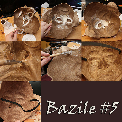
Image by Douglas R Witt
Now that Bazile is back in one particular piece, it’s time to do a little extra perform in the back of the mask. The photos in this collection have taken place more than the last 3 day… this is a time of waiting and functioning sections… it requires time for the mask to settle and dry, this function needs to be completed somewhat slowly if you are to get a mask that is not warped out of shape. There are a few things that I do to preserve it from deforming.
I use the original armature in this case it’s a plaster life cast of my teacher/actor pal Sean Daly. I place the mask back more than the plaster armature to make sure it will not warp out of face shape.
I have identified that Papier-mâching the inside of a mask must be carried out in stages… commence with the middle functions like the eyes nose and mouth… than Papier-mâché outward. Leave the rim of the mask as the final point to mâché … this can be quickly or slow… depending how massive the mask is and how considerably interior operate requirements to be done… Bazile mask is still drying 72 hours later. It’s just starting to harden…
The cause it is taken this lengthy is simply because of two variables. It’s been raining a lot here and it is made the apartment much more humid than normal, the other and the main cause is simply because I used a TP Paste (the white stuff) to fill some of the massive adverse spaces like the nose, around the eyes, ears and bottom lip. The white stuff that you are seeking at is a mixture of all-goal white glue and shredded bathroom tissue.
I use this TP Paste to fill in a couple of areas of the mask that I feel need some protection from put on and tear just in case it gets bumped although getting employed on stage. Once I have utilised the TP Paste to fill in the areas of the mask I want to straighten I will leave it to dry for 6 hours or a lot more.
Warning: this mixture should be employed sparingly since it takes a extended whilst to dry, also if you use a ton of it will make the mask heavier difficult to put on.
Even though I didn’t use extremely a lot of this Paste it will take 3 days plus to fully dry. I don’t use it quite frequently, but it’s genuinely a good thing to us to fill gaps. It’s like a mask maker’s auto physique filler to smooth some uneven exterior lumps and it strengthens the mask, I felt this mask want it and what a great chance to show you 🙂 super mask producing secretes
I do yet another six layers of Papier-mâché in the back of the masks. This will bulk up the mask a bit and give it some added stability for frequent use on stage or employing as a teaching mask. In these images the very first point I did was use the TP fill and then let it sit to settle and dry in front of a fan for 16 hours. Then I reduce out the ear holes, nostrils and trimmed the rim of the mask. As soon as I am content with the timing I Papier-mâché six layers on the interior of the mask beginning with the middle functions in the mask and worked my way outward. I did the eye, ears, nose, chin and cheek location. Then I let it settles in front of the fan for one more eight hours. Once it was dry I finished the brows and forehead and Papier-mâché the rim of the mas with smaller ribbons of paper, this will seal the mask completely and maintain it from possibly chipping for flaking apart from you are face sweat and warm breath from normal use… it also makes it appear nice.
As soon as all six layers of mâché are finish… put in front of the fan once again and let it sit and dry again for at least eight hours… there has been a lot of new work accomplished on the mask and you will notice that it will be heavier… there is due to a lot of water added to the mask and it demands to dry out and settle… put it on the armature base you sculpted the mask on and leave it sit for a day or overnight.
Now that the mask is dry… it is time to add the fabric elastic head band, you can us any kind of head band suits your fancy or whatever turns you on… String, Ribbon, leather, Fabric elastic, etc… the way to attach them is fundamentally the very same though my approach is not the only way… and you’re welcome to discover others.
For Bazile mask I am employing a half inch black fabric elastic, you can pick it up at any place that sells fabric. I use black because it disappears on stage and it by no means looks dirty. I start off by measuring a length of fabric elastic from temple to temple. Coming about the crown of the back of the head and sitting behind the ears like a pair of sunglasses. I pull the elastic just a small snug (NOT TIGHT) you want the mask to match a snuggly on your face… in the next set of photographs I will be showing how to add foam rubber to the interior of the mask so it will sit comfy on the face.
As soon as I have measured out my length of elastic set it aside and get a marker, put the mask on your face and uncover your temples on the inside of the mask. After you have marked where the elastic is going to go, use a little dab of hot glue and glue the elastic in… and try the mask on. This could take a couple of tries so use a little hot glue until you discover a comfy fit. The mask might sit on your face a bit uncomfortable… it may possibly be pressing into the corners of your eyes of sitting very snuggly to your face… that’s ok because that is what the foam rubber is for.
The discomfort will show you exactly where to put the foam… ha ha ha!
Once the mask fits snuggly it is time to use a small far more hot glue to anchor the fabric elastic into the mask, attempt to make the glue as flat as possible employing the tip of the hot gun so that you’re not obtaining poked in the temples by hot glue lumps. Then Papier-mâché three much more layers of paper over and around the fabric elastic and set the mask in front of a fan to dry for yet another six hours or so… it is essential to give the mask lots of drying time. The subsequent measures are the sealing and painting and you want a nice dry mask to perform on.
Individual artist note to newbie mask makers:
The back of the mask is just as essential as the front of the mask. Most folks think it ends with taking the mask off the mold. But if you commit a few extra hours detailing and finishing the back of the mask you are going to have a mask that will final longer and take a beating or hang on a wall without having deforming more than time.
It’s essential to also reinforce the back and fill in some of the damaging spaces… and add ventilation holes like nostrils and sometimes a modest mouth slit. This will support the actor from overheating and reduce down on sweating behind the mask. Some masks will match very close to the face and subsequently generate a vacuum impact that is like putting a plastic bag more than your face. The capacity to breath easily out of the mask is crucial it will support the actor overlook there wearing a mask, also if all you have are eyeholes as venation entrance and exit the flow of air will dry out the performer’s eyes.
Please listen to this music while viewing this set of images
youtu.be/9HtHEgINHO0
IMG_9725
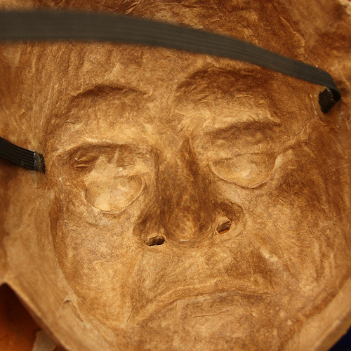
Image by Douglas R Witt
Now that Bazile is back in one piece, it is time to do a little further function in the back of the mask. The pictures in this collection have taken place more than the last 3 day… this is a time of waiting and working sections… it requires time for the mask to settle and dry, this perform demands to be carried out somewhat slowly if you are to get a mask that isn’t warped out of shape. There are a few factors that I do to maintain it from deforming.
I use the original armature in this case it is a plaster life cast of my teacher/actor buddy Sean Daly. I place the mask back over the plaster armature to make confident it will not warp out of face shape.
I have discovered that Papier-mâching the inside of a mask should be done in stages… start with the middle functions like the eyes nose and mouth… than Papier-mâché outward. Leave the rim of the mask as the last factor to mâché … this can be rapidly or slow… depending how huge the mask is and how a lot interior operate wants to be done… Bazile mask is still drying 72 hours later. It is just beginning to harden…
The cause it is taken this long is simply because of two factors. It is been raining a lot here and it is made the apartment more humid than regular, the other and the principal explanation is due to the fact I used a TP Paste (the white stuff) to fill some of the big damaging spaces like the nose, around the eyes, ears and bottom lip. The white stuff that you’re hunting at is a mixture of all-purpose white glue and shredded bathroom tissue.
I use this TP Paste to fill in a handful of regions of the mask that I really feel require some protection from wear and tear just in case it gets bumped even though being employed on stage. When I have utilized the TP Paste to fill in the areas of the mask I want to straighten I will leave it to dry for 6 hours or far more.
Warning: this mixture should be utilised sparingly simply because it takes a lengthy even though to dry, also if you use a ton of it will make the mask heavier hard to put on.
Even although I didn’t use very much of this Paste it will take 3 days plus to totally dry. I do not use it really frequently, but it’s really a good issue to us to fill gaps. It is like a mask maker’s auto body filler to smooth some uneven exterior lumps and it strengthens the mask, I felt this mask need it and what a excellent likelihood to show you 🙂 super mask making secretes
I do one more six layers of Papier-mâché in the back of the masks. This will bulk up the mask a bit and give it some added stability for frequent use on stage or employing as a teaching mask. In these images the first factor I did was use the TP fill and then let it sit to settle and dry in front of a fan for 16 hours. Then I cut out the ear holes, nostrils and trimmed the rim of the mask. After I am content with the timing I Papier-mâché six layers on the interior of the mask beginning with the middle functions in the mask and worked my way outward. I did the eye, ears, nose, chin and cheek region. Then I let it settles in front of the fan for another eight hours. As soon as it was dry I finished the brows and forehead and Papier-mâché the rim of the mas with smaller ribbons of paper, this will seal the mask entirely and preserve it from possibly chipping for flaking apart from you are face sweat and warm breath from standard use… it also tends to make it appear nice.
As soon as all six layers of mâché are finish… place in front of the fan once again and let it sit and dry once again for at least eight hours… there has been a lot of new function completed on the mask and you will notice that it will be heavier… there is due to a lot of water added to the mask and it requirements to dry out and settle… put it on the armature base you sculpted the mask on and leave it sit for a day or overnight.
Now that the mask is dry… it’s time to add the fabric elastic head band, you can us any type of head band suits your fancy or what ever turns you on… String, Ribbon, leather, Fabric elastic, etc… the way to attach them is basically the same even though my strategy is not the only way… and you are welcome to explore other individuals.
For Bazile mask I am using a half inch black fabric elastic, you can choose it up at any location that sells fabric. I use black simply because it disappears on stage and it never looks dirty. I begin off by measuring a length of fabric elastic from temple to temple. Coming about the crown of the back of the head and sitting behind the ears like a pair of sunglasses. I pull the elastic just a little snug (NOT TIGHT) you want the mask to fit a snuggly on your face… in the next set of photos I will be displaying how to add foam rubber to the interior of the mask so it will sit comfortable on the face.
As soon as I have measured out my length of elastic set it aside and get a marker, put the mask on your face and discover your temples on the inside of the mask. As soon as you have marked where the elastic is going to go, use a small dab of hot glue and glue the elastic in… and attempt the mask on. This may possibly take a few tries so use a small hot glue until you locate a comfortable fit. The mask may sit on your face a bit uncomfortable… it might be pressing into the corners of your eyes of sitting quite snuggly to your face… that’s ok since that’s what the foam rubber is for.
The pain will show you exactly where to place the foam… ha ha ha!
When the mask fits snuggly it is time to use a small far more hot glue to anchor the fabric elastic into the mask, attempt to make the glue as flat as attainable using the tip of the hot gun so that you’re not receiving poked in the temples by hot glue lumps. Then Papier-mâché 3 much more layers of paper over and about the fabric elastic and set the mask in front of a fan to dry for an additional 6 hours or so… it is essential to give the mask lots of drying time. The next methods are the sealing and painting and you want a nice dry mask to operate on.
Individual artist note to beginner mask makers:
The back of the mask is just as critical as the front of the mask. Most men and women feel it ends with taking the mask off the mold. But if you devote a couple of extra hours detailing and finishing the back of the mask you’re going to have a mask that will final longer and take a beating or hang on a wall without having deforming over time.
It’s essential to also reinforce the back and fill in some of the adverse spaces… and add ventilation holes like nostrils and often a modest mouth slit. This will assist the actor from overheating and reduce down on sweating behind the mask. Some masks will fit extremely close to the face and subsequently produce a vacuum effect that is like putting a plastic bag over your face. The potential to breath easily out of the mask is crucial it will support the actor overlook there wearing a mask, also if all you have are eyeholes as venation entrance and exit the flow of air will dry out the performer’s eyes.
Please listen to this music although viewing this set of pictures
youtu.be/9HtHEgINHO0
Bazile (27)
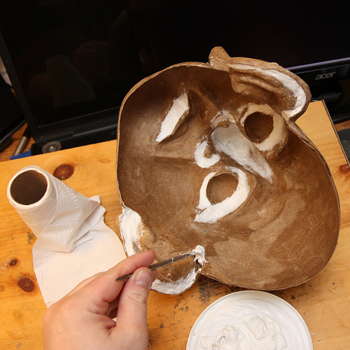
Image by Douglas R Witt
Now that Bazile is back in one piece, it’s time to do a small added work in the back of the mask. The images in this collection have taken location over the last three day… this is a time of waiting and functioning sections… it requires time for the mask to settle and dry, this work requirements to be carried out somewhat slowly if you are to get a mask that isn’t warped out of shape. There are a few items that I do to hold it from deforming.
I use the original armature in this case it’s a plaster life cast of my teacher/actor buddy Sean Daly. I place the mask back more than the plaster armature to make sure it will not warp out of face shape.
I have located that Papier-mâching the inside of a mask must be accomplished in stages… start off with the middle features like the eyes nose and mouth… than Papier-mâché outward. Leave the rim of the mask as the last thing to mâché … this can be quick or slow… based how massive the mask is and how significantly interior operate demands to be done… Bazile mask is nevertheless drying 72 hours later. It is just beginning to harden…
The explanation it’s taken this lengthy is due to the fact of two variables. It is been raining a lot right here and it is created the apartment far more humid than typical, the other and the primary cause is because I used a TP Paste (the white stuff) to fill some of the large adverse spaces like the nose, around the eyes, ears and bottom lip. The white stuff that you are hunting at is a mixture of all-objective white glue and shredded bathroom tissue.
I use this TP Paste to fill in a handful of areas of the mask that I really feel need some protection from wear and tear just in case it gets bumped although getting utilised on stage. When I have used the TP Paste to fill in the places of the mask I want to straighten I will leave it to dry for 6 hours or far more.
Warning: this mixture should be utilized sparingly simply because it requires a long while to dry, also if you use a ton of it will make the mask heavier hard to wear.
Even although I didn’t use really much of this Paste it will take three days plus to fully dry. I don’t use it extremely frequently, but it’s genuinely a very good issue to us to fill gaps. It’s like a mask maker’s auto physique filler to smooth some uneven exterior lumps and it strengthens the mask, I felt this mask want it and what a fantastic likelihood to show you 🙂 super mask generating secretes
I do an additional six layers of Papier-mâché in the back of the masks. This will bulk up the mask a bit and give it some added stability for frequent use on stage or utilizing as a teaching mask. In these photos the first factor I did was use the TP fill and then let it sit to settle and dry in front of a fan for 16 hours. Then I reduce out the ear holes, nostrils and trimmed the rim of the mask. When I am happy with the timing I Papier-mâché six layers on the interior of the mask starting with the middle attributes in the mask and worked my way outward. I did the eye, ears, nose, chin and cheek location. Then I let it settles in front of the fan for yet another 8 hours. After it was dry I completed the brows and forehead and Papier-mâché the rim of the mas with smaller sized ribbons of paper, this will seal the mask fully and preserve it from possibly chipping for flaking apart from you are face sweat and warm breath from normal use… it also makes it look good.
As soon as all six layers of mâché are finish… put in front of the fan again and let it sit and dry once more for at least eight hours… there has been a lot of new perform carried out on the mask and you will notice that it will be heavier… there is due to a lot of water added to the mask and it demands to dry out and settle… place it on the armature base you sculpted the mask on and leave it sit for a day or overnight.
Now that the mask is dry… it is time to add the fabric elastic head band, you can us any type of head band suits your fancy or whatever turns you on… String, Ribbon, leather, Fabric elastic, etc… the way to attach them is generally the very same although my strategy is not the only way… and you are welcome to explore other individuals.
For Bazile mask I am employing a half inch black fabric elastic, you can pick it up at any location that sells fabric. I use black simply because it disappears on stage and it in no way looks dirty. I commence off by measuring a length of fabric elastic from temple to temple. Coming around the crown of the back of the head and sitting behind the ears like a pair of sunglasses. I pull the elastic just a small snug (NOT TIGHT) you want the mask to fit a snuggly on your face… in the subsequent set of pictures I will be displaying how to add foam rubber to the interior of the mask so it will sit comfy on the face.
After I have measured out my length of elastic set it aside and get a marker, put the mask on your face and uncover your temples on the inside of the mask. As soon as you have marked exactly where the elastic is going to go, use a tiny dab of hot glue and glue the elastic in… and try the mask on. This may take a few tries so use a tiny hot glue until you locate a comfortable match. The mask may sit on your face a bit uncomfortable… it may possibly be pressing into the corners of your eyes of sitting extremely snuggly to your face… that’s ok because that is what the foam rubber is for.
The pain will show you where to place the foam… ha ha ha!
When the mask fits snuggly it’s time to use a little more hot glue to anchor the fabric elastic into the mask, attempt to make the glue as flat as feasible employing the tip of the hot gun so that you’re not acquiring poked in the temples by hot glue lumps. Then Papier-mâché three more layers of paper more than and about the fabric elastic and set the mask in front of a fan to dry for another 6 hours or so… it is crucial to give the mask lots of drying time. The next methods are the sealing and painting and you want a good dry mask to function on.
Person artist note to newbie mask makers:
The back of the mask is just as essential as the front of the mask. Most men and women think it ends with taking the mask off the mold. But if you devote a handful of added hours detailing and finishing the back of the mask you’re going to have a mask that will last longer and take a beating or hang on a wall without deforming over time.
It’s crucial to also reinforce the back and fill in some of the adverse spaces… and add ventilation holes like nostrils and at times a little mouth slit. This will aid the actor from overheating and reduce down on sweating behind the mask. Some masks will match extremely close to the face and subsequently create a vacuum impact that is like placing a plastic bag more than your face. The capacity to breath effortlessly out of the mask is important it will help the actor overlook there wearing a mask, also if all you have are eyeholes as venation entrance and exit the flow of air will dry out the performer’s eyes.
Please listen to this music whilst viewing this set of images
youtu.be/9HtHEgINHO0