Cool Plastic Auto Exterior Mold images

Cool Plastic Auto Exterior Mold images

Some cool plastic auto exterior mold images:

Bazile (33)
plastic auto exterior mold
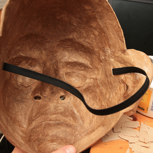
Image by Douglas R Witt
Now that Bazile is back in one piece, it’s time to do a little extra work in the back of the mask. The photos in this collection have taken place over the last three day… this is a time of waiting and working sections… it takes time for the mask to settle and dry, this work needs to be done somewhat slowly if you are to get a mask that isn’t warped out of shape. There are a few things that I do to keep it from deforming.

I use the original armature in this case it’s a plaster life cast of my teacher/actor friend Sean Daly. I put the mask back over the plaster armature to make sure it will not warp out of face shape.

I have found that Papier-mâching the inside of a mask must be done in stages… start with the middle features like the eyes nose and mouth… than Papier-mâché outward. Leave the rim of the mask as the last thing to mâché … this can be fast or slow… depending how large the mask is and how much interior work needs to be done… Bazile mask is still drying 72 hours later. It’s just starting to harden…

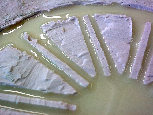
The reason it’s taken this long is because of two factors. It’s been raining a lot here and it’s made the apartment more humid than normal, the other and the main reason is because I used a TP Paste (the white stuff) to fill some of the large negative spaces like the nose, around the eyes, ears and bottom lip. The white stuff that you’re looking at is a mixture of all-purpose white glue and shredded bathroom tissue.

I use this TP Paste to fill in a few areas of the mask that I feel need some protection from wear and tear just in case it gets bumped while being used on stage. Once I have used the TP Paste to fill in the areas of the mask I want to straighten I will leave it to dry for 6 hours or more.

Warning: this mixture should be used sparingly because it takes a long while to dry, also if you use a ton of it will make the mask heavier hard to wear.

Even though I didn’t use very much of this Paste it will take three days plus to fully dry. I don’t use it very often, but it’s really a good thing to us to fill gaps. It’s like a mask maker’s auto body filler to smooth some uneven exterior lumps and it strengthens the mask, I felt this mask need it and what a great chance to show you 🙂 super mask making secretes

I do another six layers of Papier-mâché in the back of the masks. This will bulk up the mask a bit and give it some extra stability for frequent use on stage or using as a teaching mask. In these photos the first thing I did was use the TP fill and then let it sit to settle and dry in front of a fan for 16 hours. Then I cut out the ear holes, nostrils and trimmed the rim of the mask. Once I am happy with the timing I Papier-mâché six layers on the interior of the mask starting with the middle features in the mask and worked my way outward. I did the eye, ears, nose, chin and cheek area. Then I let it settles in front of the fan for another 8 hours. Once it was dry I finished the brows and forehead and Papier-mâché the rim of the mas with smaller ribbons of paper, this will seal the mask completely and keep it from possibly chipping for flaking apart from you’re face sweat and warm breath from regular use… it also makes it look nice.

Once all six layers of mâché are finish… put in front of the fan again and let it sit and dry again for at least 8 hours… there has been a lot of new work done on the mask and you will notice that it will be heavier… there is due to a lot of water added to the mask and it needs to dry out and settle… put it on the armature base you sculpted the mask on and leave it sit for a day or overnight.

Now that the mask is dry… it’s time to add the fabric elastic head band, you can us any kind of head band suits your fancy or whatever turns you on… String, Ribbon, leather, Fabric elastic, etc… the way to attach them is basically the same although my method is not the only way… and you’re welcome to explore others.
For Bazile mask I am using a half inch black fabric elastic, you can pick it up at any place that sells fabric. I use black because it disappears on stage and it never looks dirty. I start off by measuring a length of fabric elastic from temple to temple. Coming around the crown of the back of the head and sitting behind the ears like a pair of sunglasses. I pull the elastic just a little snug (NOT TIGHT) you want the mask to fit a snuggly on your face… in the next set of photos I will be showing how to add foam rubber to the interior of the mask so it will sit comfortable on the face.

Once I have measured out my length of elastic set it aside and get a marker, put the mask on your face and find your temples on the inside of the mask. Once you have marked where the elastic is going to go, use a little dab of hot glue and glue the elastic in… and try the mask on. This may take a few tries so use a little hot glue until you find a comfortable fit. The mask may sit on your face a bit uncomfortable… it may be pressing into the corners of your eyes of sitting very snuggly to your face… that’s ok because that’s what the foam rubber is for.

The pain will show you where to put the foam… ha ha ha!

Once the mask fits snuggly it’s time to use a little more hot glue to anchor the fabric elastic into the mask, try to make the glue as flat as possible using the tip of the hot gun so that you’re not getting poked in the temples by hot glue lumps. Then Papier-mâché three more layers of paper over and around the fabric elastic and set the mask in front of a fan to dry for another 6 hours or so… it’s important to give the mask lots of drying time. The next steps are the sealing and painting and you want a nice dry mask to work on.

Person artist note to beginner mask makers:
The back of the mask is just as important as the front of the mask. Most people think it ends with taking the mask off the mold. But if you spend a few extra hours detailing and finishing the back of the mask you’re going to have a mask that will last longer and take a beating or hang on a wall without deforming over time.

It’s important to also reinforce the back and fill in some of the negative spaces… and add ventilation holes like nostrils and sometimes a small mouth slit. This will help the actor from overheating and cut down on sweating behind the mask. Some masks will fit very close to the face and subsequently create a vacuum effect that is like putting a plastic bag over your face. The ability to breath easily out of the mask is important it will help the actor forget there wearing a mask, also if all you have are eyeholes as venation entrance and exit the flow of air will dry out the performer’s eyes.

Please listen to this music while viewing this set of photos
youtu.be/9HtHEgINHO0

Cool Automotive Mold Design images

Cool Automotive Mold Design images

Some cool automotive mold design images:

1969 Lotus Europa S2 (09)
automotive mold design
Image by Georg Sander
The Lotus Europa was a two door mid-engined GT coupé built by Lotus Cars from 1966 to 1975. In 2006 Lotus began production of a totally new, Lotus Elise-derived design, a mid-engined GT coupé named Europa S.

The original Europa used Lotus founder Colin Chapman’s minimalist steel backbone chassis that was first used in the Lotus Elan, while also relying on its fibreglass moulded body for structural strength. The Europa was based on a prototype built to compete for Henry Ford II’s contract to build a Le Mans race car in the early 1960s.

The Europa was designed and built to be an embodiment of Chapman’s oft-stated philosophy of automotive design: "Simplify, then add lightness."

(Wikipedia)

– – –

Der Europa, im Dezember 1966 vorgestellt, war ursprünglich nur für die ausländischen (nicht-UK) Märkte bestimmt. Die ersten Fahrzeuge wurden nach Frankreich und in die Schweiz verkauft. Er verfügte über den gleichen Motor wie der Renault 16, jedoch war er hinter der Fahrgastzelle als Mittelmotor eingebaut. Dies verlieh dem Europa eine Straßenlage und Fahreigenschaften die eines Rennwagens würdig waren, auch sein Rahmen war für Motoren mit mehr als nur 1470 cm³ ausgelegt. Die Karosserie aus glasfaserverstärktem Polyester war mit einem Zentralträgerchassis aus Stahlblech zu einem geschlossenem Chassis verklebt. Diese Kombination war Voraussetzung für die hervorragenden Fahreigenschaften. Nur 296 Exemplare des ursprünglichen S1 (auf Basis des Grundgedankens des Lotus Gründers Colin Chapman ) wurden gebaut (Chassis Nummer 460001 bis 460296). Diese Fahrzeuge bestanden aus einer extrem minimalistischen Konstruktion, mit geschlossenen Seitenfenstern, festen Sitzen (nur die Pedale waren verstellbar), kaum Türverkleidungen und einfachen Aluminiuminstrumenten.

Ab 1969, anlässlich des Erscheinens der zweiten Serie (Europa S2), wurden Chassis und Karosserie miteinander verschraubt, was jedoch auch die ursprünglichen Fahreigenschaften änderte. Gleichzeitig wurde für den amerikanischen Markt ein Motor mit 1565 cm³ eingeführt. 1971 wurde der Europa TwinCam vorgestellt, der über einen Motor mit zwei Nockenwellen im Leichtmetallkopf und 1558 cm³ verfügte, wie er bereits im Lotus Elan eingebaut wurde. Ein Jahr später ging man zur leistungsgesteigerten Version „Big Valve“ (ähnlich wie beim Lotus Elan Sprint) über und verband ihn mit einem Renault 5-Gang-Getriebe. Diese neue Ausführung nannte man Europa Special.

(Wikipedia)

Steven F. Udvar-Hazy Center: P-40 Warhawk, SR-71 Blackbird, Naval Aircraft Factory N3N seaplane, Space Shuttle Enterprise

Steven F. Udvar-Hazy Center: P-40 Warhawk, SR-71 Blackbird, Naval Aircraft Factory N3N seaplane, Space Shuttle Enterprise

A few nice plastic auto handle china images I found:

Steven F. Udvar-Hazy Center: P-40 Warhawk, SR-71 Blackbird, Naval Aircraft Factory N3N seaplane, Space Shuttle Enterprise
plastic auto handle china
Image by Chris Devers
Quoting Smithsonian National Air and Space Museum | Curtiss P-40E Warhawk (Kittyhawk IA):

Whether known as the Warhawk, Tomahawk, or Kittyhawk, the Curtiss P-40 proved to be a successful, versatile fighter during the first half of World War II. The shark-mouthed Tomahawks that Gen. Claire Chennault’s "Flying Tigers" flew in China against the Japanese remain among the most popular airplanes of the war. P-40E pilot Lt. Boyd D. Wagner became the first American ace of World War II when he shot down six Japanese aircraft in the Philippines in mid-December 1941.

Curtiss-Wright built this airplane as Model 87-A3 and delivered it to Canada as a Kittyhawk I in 1941. It served until 1946 in No. 111 Squadron, Royal Canadian Air Force. U.S. Air Force personnel at Andrews Air Force Base restored it in 1975 to represent an aircraft of the 75th Fighter Squadron, 23rd Fighter Group, 14th Air Force.

Donated by the Exchange Club in Memory of Kellis Forbes.

Manufacturer:
Curtiss Aircraft Company

Date:
1939

Country of Origin:
United States of America

Dimensions:
Overall: 330 x 970cm, 2686kg, 1140cm (10ft 9 15/16in. x 31ft 9 7/8in., 5921.6lb., 37ft 4 13/16in.)

Materials:
All-metal, semi-monocoque

Physical Description:
Single engine, single seat, fighter aircraft.

• • • • •

See more photos of this, and the Wikipedia article.

Details, quoting from Smithsonian National Air and Space Museum | Lockheed SR-71 Blackbird:

No reconnaissance aircraft in history has operated globally in more hostile airspace or with such complete impunity than the SR-71, the world’s fastest jet-propelled aircraft. The Blackbird’s performance and operational achievements placed it at the pinnacle of aviation technology developments during the Cold War.

This Blackbird accrued about 2,800 hours of flight time during 24 years of active service with the U.S. Air Force. On its last flight, March 6, 1990, Lt. Col. Ed Yielding and Lt. Col. Joseph Vida set a speed record by flying from Los Angeles to Washington, D.C., in 1 hour, 4 minutes, and 20 seconds, averaging 3,418 kilometers (2,124 miles) per hour. At the flight’s conclusion, they landed at Washington-Dulles International Airport and turned the airplane over to the Smithsonian.

Transferred from the United States Air Force.

Manufacturer:
Lockheed Aircraft Corporation

Designer:
Clarence L. "Kelly" Johnson

Date:
1964

Country of Origin:
United States of America

Dimensions:
Overall: 18ft 5 15/16in. x 55ft 7in. x 107ft 5in., 169998.5lb. (5.638m x 16.942m x 32.741m, 77110.8kg)
Other: 18ft 5 15/16in. x 107ft 5in. x 55ft 7in. (5.638m x 32.741m x 16.942m)

Materials:
Titanium

Physical Description:
Twin-engine, two-seat, supersonic strategic reconnaissance aircraft; airframe constructed largley of titanium and its alloys; vertical tail fins are constructed of a composite (laminated plastic-type material) to reduce radar cross-section; Pratt and Whitney J58 (JT11D-20B) turbojet engines feature large inlet shock cones.

• • • • •

Quoting Smithsonian National Air and Space Museum | Naval Aircraft Factory N3N:

In 1934 the Naval Aircraft Factory in Philadelphia was tasked to manufacture a new primary trainer for the U.S. Navy. Following successful tests, this little biplane trainer was built in both land and seaplane versions. The Navy initially ordered 179 N3N-1 models, and the factory began producing more than 800 N3N-3 models in 1938. U.S. Navy primary flight training schools used N3Ns extensively throughout World War II. A few of the seaplane version were retained for primary training at the U.S. Naval Academy. In 1961 they became the last biplanes retired from U.S. military service.

This N3N-3 was transferred from Cherry Point to Annapolis in 1946, where it served as a seaplane trainer. It was restored and displayed at the Naval Academy Museum before being transferred here.

Transferred from the United States Navy

Manufacturer:
Naval Aircraft Factory

Date:
1941

Country of Origin:
United States of America

Dimensions:
Overall: 10ft 9 15/16in. x 25ft 7 1/16in. x 34ft 1 7/16in., 2090lb. (330 x 780 x 1040cm, 948kg)

Materials:
bolted steel-tube fuselage construction with removable side panels wings, also constructed internally of all metal, covered with fabric like the fuselage and tail.

Physical Description:
Bright yellow bi-plane, hand crank start. Cockpit instrumentation consists of an altimeter, tachometer, airspeed indicator, compass, turn and bank indicator, and a combination fuel and oil temperature and pressure gauge, floats.

• • • • •

See more photos of this, and the Wikipedia article.

Details, quoting from Smithsonian National Air and Space Museum | Space Shuttle Enterprise:

Manufacturer:
Rockwell International Corporation

Country of Origin:
United States of America

Dimensions:
Overall: 57 ft. tall x 122 ft. long x 78 ft. wing span, 150,000 lb.
(1737.36 x 3718.57 x 2377.44cm, 68039.6kg)

Materials:
Aluminum airframe and body with some fiberglass features; payload bay doors are graphite epoxy composite; thermal tiles are simulated (polyurethane foam) except for test samples of actual tiles and thermal blankets.

The first Space Shuttle orbiter, "Enterprise," is a full-scale test vehicle used for flights in the atmosphere and tests on the ground; it is not equipped for spaceflight. Although the airframe and flight control elements are like those of the Shuttles flown in space, this vehicle has no propulsion system and only simulated thermal tiles because these features were not needed for atmospheric and ground tests. "Enterprise" was rolled out at Rockwell International’s assembly facility in Palmdale, California, in 1976. In 1977, it entered service for a nine-month-long approach-and-landing test flight program. Thereafter it was used for vibration tests and fit checks at NASA centers, and it also appeared in the 1983 Paris Air Show and the 1984 World’s Fair in New Orleans. In 1985, NASA transferred "Enterprise" to the Smithsonian Institution’s National Air and Space Museum.

Transferred from National Aeronautics and Space Administration

Nice Automotive Parts Mold photos

Nice Automotive Parts Mold photos

Some cool automotive parts mold images:

Kevlar fibre composite shear surface
automotive parts mold
Image by CORE-Materials
DoITPoMS, University of Cambridge

This is an image of the shear surface in a failed composite beam. ‘Hackles’ of matrix are clearly visible where shear has occurred within the matrix and it is also clear that shear has occurred across the fibre/matrix interface. The fibres are for the most part totally unscathed, though some mis-aligned fibres have become caught between the shear surfaces and ‘fibrillated’ by rolling and bending actions. It may be that this failure mechanism has been partly inhibited by poor fibre alignment since some off-axis fibres will reinforce the matrix in shear. It will have been promoted, however, by the extensive longitudinal voids.

System
Kevlar composite

Composition
Kevlar fibre, epoxy resin matrix

Reaction
Kevlar is a lyotropic liquid crystal polymer. This means that it can be readily processed in solution (in this case, sulphuric acid). It is annealed under tension to increase its elastic modulus

Processing
A crude Kevlar composite was made by laying out 40 tows of fibre, painting them with epoxy resin, compressing them in a mould, and curing them for five hours at 100-190 degrees C

Applications
Kevlar composites are used as a structural material in the aerospace and automotive industries, as well as in certain high-performance sporting equipment. They present exceptional stiffness and can be structurally optimised for particular load-bearing applications.

Sample preparation
The bar has been bent to failure in a three-point bending rig.

Technique
Scanning electron microscopy (SEM)

Contributor
J A Curran

Organisation
Department of Materials Science and Metallurgy, University of Cambridge

View micrograph in DoITPoMS website

Image from page 935 of “Automotive industries” (1899)
automotive parts mold
Image by Internet Archive Book Images
Identifier: automotiveindust44phil
Title: Automotive industries
Year: 1899 (1890s)
Authors:
Subjects: Automobiles Aeronautics
Publisher: Philadelphia [etc.] Chilton [etc.]
Contributing Library: Engineering – University of Toronto
Digitizing Sponsor: University of Toronto

View Book Page: Book Viewer
About This Book: Catalog Entry
View All Images: All Images From Book

Click here to view book online to see this illustration in context in a browseable online version of this book.

Text Appearing Before Image:
(1) One of a battery of four modern electric furnaces with a daily capacity of slif/htly more than 150 tons. (2) Pouring■ ■■:,■■■■ •■/ into ,„,,,,/ moulds ,„ the Timhen steel will. ( ?,, 11 ,,,1 ran I ir press ami electric manipulator where inuots arepressed into blooms. (4) Twenty-two inch, three stand rolling mill and tilting tables where blooms are converted intorounds and squares with a size range of from 2 in. to 6% in. (5) Twelve inch, three-stand rolling mill where bars for rollsare converted into coils and small rods. (6) Piercing mill where bars are converted into seamless tubes. 914 AUTOMOTIVE INDUSTRIESTHE AUTOMOBILE April 28, 1921

Text Appearing After Image:
there pierced seamless tubes are automatically finished. (8) Straightening machine where finished traii/lttened. (9) Bulldozer for fabrication of formed seamless tubes. (10) Part of the screw machine nibesare fabricated on automatic screw machines into green cups and cones. (11) Four spindle roller fuhrictihit,/ much nies where rods tire fabricated al high speed into <• rarictij a) si cs o) rolls held to much tiling tolerances not in excess of .003 of an inch. (12) Another view of the screw machine department where large cups and cones made from forgings are machined on automatic screw machines. (7) Reducing millseamless tubes aredepartment win re tul April 28, 1921 AUTOMOTIVE INDUSTRIES THE AUTOMOBILE 915

Note About Images
Please note that these images are extracted from scanned page images that may have been digitally enhanced for readability – coloration and appearance of these illustrations may not perfectly resemble the original work.

4 remaining days of Major Project
automotive parts mold
Image by Matty Ring
The whiter coloured material is a mould made of silicon rubber, for the rims on my car. the yellow material is two part plastic.