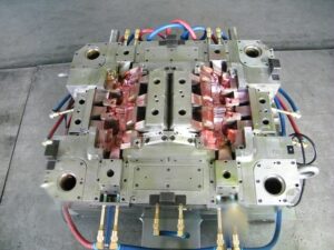
Ejector sleeves

The capacity of a stripper plate is like that of an ejector sleeve, in that both are normally used to push on a fringe of the shaped part. The plan of the stripper plate shifts essentially, in any case, since it regularly pushes on most or the entirety of the whole fringe of the formed part(s). Thus, the stripper plate has an altogether bigger territory than a solitary ejector sleeve and a totally unique development.
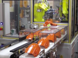
The compressive pressure in ejector cutting edges and the forced shear weight on the trim by the ejector sharp edges don’t for the most part oblige the plan of the ejector edges.

Because of their little thickness, notwithstanding, clasping can be a worry. Hence, the thickness of the ejector edge should approach the full thickness of the rib. The clasping is as yet represented by oem/odm automotives injection molding factory, however with the snapshot of latency characterized for a rectangular segment.

The capacity of an ejector sleeve is like that of an ejector sharp edge, in that both are commonly used to push on a vertical segment of the shaped part, The plan of the ejector sleeve shifts altogether, notwithstanding, since it is an empty chamber that slides along a fixed center pin to give a discharge power at the base surface of a formed chief. Ejector pinnacle sleeves are extremely compelling segments for part discharge, since they push on a firm managers in the part at an area where rubbing powers between the embellishment and the center happen.

An average ejector sleeve get together plan is given in high precision plastic making mould suppliers china, In this plan, an exceptionally conductive center pin is situated in the back clasp plate and made sure about with an attachment head set screw. The center pin goes through the back brace plate, ejector plate, ejector retainer plate, uphold plate, and center addition to burrow out the ideal part of the shape pit, The ejector peak sleeve is held by the ejector retainer plate and goes through the help plate and center supplement. In the plan of detail A, the finish of the ejector sleeve is coplanar with the highest point of the chief and the nearby rib.

Given the annular math and enormous snapshot of idleness for ejector sleeves, there are normally no issues identified with pressure or clasping. Notwithstanding, the point by point plan of the ejector sleeve is particularly basic since it slides along between a fixed center pin and the fixed center supplement. The pivotal area of the ejector sleeve is administered by the concentric mating of the ejector sleeve with the ejector opening in the center addition. Since the center pin is inner to the sleeve, the divider thickness and concentricity of the trim around the center pin is represented by the resilience stack-up of the ejector opening, ejector sleeve, and center pin. To decrease dimensional varieties in the shaped part, clearances for venting should be limited.
oem mold factory give instances of clearances in the different form plates. The form fashioner ought to guarantee that the center pin has a reasonable freedom through the ejector plate and ejector retainer plate, in any case a slight absence of concentricity between the ejector sleeve and center pin may make the sleeve tie.

This article is from http://www.automoldchina.com/
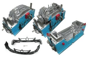
Ejection System

The ejection system is answerable for eliminating the formed part(s) from the shape after the shape opens. While this may appear to be a basic capacity, the intricacy of the ejection system can shift broadly relying upon the prerequisites of the embellishment application. Numerous issues must be considered including the requirement for various tomahawks of activation, the size and appropriation of the ejection powers, and others to get the automotive molds made in china. Prior to starting the examination and plan of the ejection system, an outline of its capacity is first given.

China industrial injection moulding manufacturers gives a side perspective on a form opening for the resulting ejection of the PC bezel. The ejector gathering (comprising of the ejector plate, ejector retainer plate, return pins, ejector pins, stop pins, and different parts) is housed between the back cinch plate, uphold plate, and rails.

Right now in the embellishment cycle, the shaped part has contracted onto the center side of the form and has been pulled from the form pit as the moving side of the form is withdrawn from the fixed side of the form. In almost no time, the trim machine will push the ejector take out bar against the ejector plate to incite the ejector gathering and strip the formed parts off the center. Right now, be that as it may, a freedom exists between the ejector take out bar and the ejector plate.

Plastic precision injection mould manufacturers china gives a side perspective on the form during the incitation of the discharge system. Preceding discharge, the ejection of the embellishment machine platens isolated the two shape parts to permit freedom for the discharge of the part. The machine at that point drives the ejector take out bar forward to connect with the back surface of the ejector plate. Since the machine can give a power to the take out bar a lot more noteworthy than the power with which the moldings have contracted onto the center, the whole ejector get together is constrained forward. The ejector pins come into contact with the formed part(s) and push the molding(s) off the center.

After the moldings are ejectioned out, the embellishment machine at that point withdraws the ejector take out bar as appeared in oem/odm automatives injection molding design factory. A freedom is then made between the front of the take out pole and the rear of the ejector plate, which permits the ejector get together to be reset to its unique situation for the following trim cycle.

There are a few different ways of resetting the ejector system, which will be talked about later. In any case, one regular strategy for restoring the ejector gathering is to just close the form as appeared in precision molds made in china. The front surface of the return pins will at that point contact the contradicting face of the A plate. The back surface of the return pins will at that point drive the ejector plate, ejector retainer plate, and all the ejector sticks in reverse as the form closes.

The plastic moldings will in general psychologist during cooling and will ordinarily stay on the shape centers upon the kickoff of the form. All things considered, systems are needed to push the parts off the shape during the ejection stage. While this essential capacity is handily perceived, there are a few related plan destinations that ought to be fulfilled in the plan of the ejection system.

This article is from http://www.automoldchina.com

Cooling Line Network

At the point when molds have more than one cooling line, an issue will emerge with regards to how the trim machine administrator will associate the shape to the form temperature regulator. Think about the PC bezel, overlaid with cooling lines as appeared in plastic precision injection mould manufacturers china.

The shape has been furnished with eight cooling lines crossing over the width of the form hole. Confronted with eight cooling line associations, the machine administrator may utilize short hoses to circle the cooling lines as appeared. Such an arrangement has two intensifying issues. To start with, the stream obstruction through the consolidated length of all the cooling lines can be incredibly high, decreasing the coolant stream rates per Eq. .9.16. Second, the form coolant temperature can increment along the length of the cooling circuit at decreased coolant stream rates. Accordingly, a noteworthy temperature differential can emerge from where the coolant enters the shape to where the coolant leaves the form.

Mindful of this issue, numerous if not most decays have coolant manifolds introduced on the trim machine between the shape temperature regulator and the form. The administrator would then be able to utilize longer cooling hoses to separately associate two arrangements of Cooling lines with a short profit circle for the contrary side of the form. Such an equal arrangement is appeared in newest double coler mold parts. This design is very basic since it is basic and gives viable cooling. Notwithstanding, the establishment and expulsion of the form from the machine is muddled by the quantity of lines that must be associated and separated. The high number of hoses and administrator steps additionally improves the probability that the cooling framework might be arrangement mistakenly or fizzle, for example, because of an approximately associated hose.

There is as of now a lot of enthusiasm for the plastics business in lean assembling, which places noteworthy accentuation on decreased cycle intricacy and arrangement times [14-16]. By putting somewhat more in the infusion shape, it is conceivable to decrease the form arrangement time, lessen potential disappointment modes, and improve the form execution. Injection mould manufacturers shows the expansion of two vertical cooling lines interfacing each of the eight flat lines inside the infusion shape; twenty weight plugs have been introduced to hinder the coolant stream at chosen areas. The outcome is that a cooling complex has been planned inward to the form, with the end goal that lone two associations are required. Simultaneously, the cooling consistency is expanded. This inside complex plan has almost no additional expense while conveying both expanded execution and convenience.

Once stopping is viewed as a choice in the steering of cooling lines, a lot more intricate cooling line format become accessible. In the cooling framework plans for the bezel appeared in china standard components for injection mold, the part of the cooling lines situated inside the screen region of the bezel isn’t eliminating any huge warmth. In the event that a two-plate form with a cool sprinter is utilized as appeared in oem/odm automatives injection molding design factory, at that point these cooling lines would cool the sprue and sprinters. For a three-plate or hot sprinter shape, be that as it may, there is no warmth being produced in the focal region of the form cavity. Given that there is no requirement for cooling in the focal point of the form, it is conceivable to course the cooling lines around the outskirts of the part to improve the cooling of the shape hole while lessening oem/odm injection moulding tooling costs and giving a shape that is considerably simpler to work.

This plan gives usability, moderate stream obstruction, and uniform cooling about the whole embellishment.

This article is from http://www.automoldchina.com