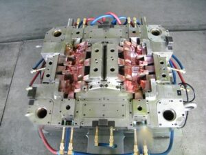
At the point when molds have more than one cooling line, an issue will emerge with regards to how the trim machine administrator will associate the shape to the form temperature regulator. Think about the PC bezel, overlaid with cooling lines as appeared in plastic precision injection mould manufacturers china.
The shape has been furnished with eight cooling lines crossing over the width of the form hole. Confronted with eight cooling line associations, the machine administrator may utilize short hoses to circle the cooling lines as appeared. Such an arrangement has two intensifying issues. To start with, the stream obstruction through the consolidated length of all the cooling lines can be incredibly high, decreasing the coolant stream rates per Eq. .9.16. Second, the form coolant temperature can increment along the length of the cooling circuit at decreased coolant stream rates. Accordingly, a noteworthy temperature differential can emerge from where the coolant enters the shape to where the coolant leaves the form.
Mindful of this issue, numerous if not most decays have coolant manifolds introduced on the trim machine between the shape temperature regulator and the form. The administrator would then be able to utilize longer cooling hoses to separately associate two arrangements of Cooling lines with a short profit circle for the contrary side of the form. Such an equal arrangement is appeared in newest double coler mold parts. This design is very basic since it is basic and gives viable cooling. Notwithstanding, the establishment and expulsion of the form from the machine is muddled by the quantity of lines that must be associated and separated. The high number of hoses and administrator steps additionally improves the probability that the cooling framework might be arrangement mistakenly or fizzle, for example, because of an approximately associated hose.
There is as of now a lot of enthusiasm for the plastics business in lean assembling, which places noteworthy accentuation on decreased cycle intricacy and arrangement times [14-16]. By putting somewhat more in the infusion shape, it is conceivable to decrease the form arrangement time, lessen potential disappointment modes, and improve the form execution. Injection mould manufacturers shows the expansion of two vertical cooling lines interfacing each of the eight flat lines inside the infusion shape; twenty weight plugs have been introduced to hinder the coolant stream at chosen areas. The outcome is that a cooling complex has been planned inward to the form, with the end goal that lone two associations are required. Simultaneously, the cooling consistency is expanded. This inside complex plan has almost no additional expense while conveying both expanded execution and convenience.
Once stopping is viewed as a choice in the steering of cooling lines, a lot more intricate cooling line format become accessible. In the cooling framework plans for the bezel appeared in china standard components for injection mold, the part of the cooling lines situated inside the screen region of the bezel isn’t eliminating any huge warmth. In the event that a two-plate form with a cool sprinter is utilized as appeared in oem/odm automatives injection molding design factory, at that point these cooling lines would cool the sprue and sprinters. For a three-plate or hot sprinter shape, be that as it may, there is no warmth being produced in the focal region of the form cavity. Given that there is no requirement for cooling in the focal point of the form, it is conceivable to course the cooling lines around the outskirts of the part to improve the cooling of the shape hole while lessening oem/odm injection moulding tooling costs and giving a shape that is considerably simpler to work.
This plan gives usability, moderate stream obstruction, and uniform cooling about the whole embellishment.
This article is from http://www.automoldchina.com