Ejector sleeves

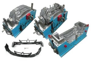
The capacity of a stripper plate is like that of an ejector sleeve, in that both are normally used to push on a fringe of the shaped part. The plan of the stripper plate shifts essentially, in any case, since it regularly pushes on most or the entirety of the whole fringe of the formed part(s). Thus, the stripper plate has an altogether bigger territory than a solitary ejector sleeve and a totally unique development.

The compressive pressure in ejector cutting edges and the forced shear weight on the trim by the ejector sharp edges don’t for the most part oblige the plan of the ejector edges.

Because of their little thickness, notwithstanding, clasping can be a worry. Hence, the thickness of the ejector edge should approach the full thickness of the rib. The clasping is as yet represented by oem/odm automotives injection molding factory, however with the snapshot of latency characterized for a rectangular segment.

The capacity of an ejector sleeve is like that of an ejector sharp edge, in that both are commonly used to push on a vertical segment of the shaped part, The plan of the ejector sleeve shifts altogether, notwithstanding, since it is an empty chamber that slides along a fixed center pin to give a discharge power at the base surface of a formed chief. Ejector pinnacle sleeves are extremely compelling segments for part discharge, since they push on a firm managers in the part at an area where rubbing powers between the embellishment and the center happen.

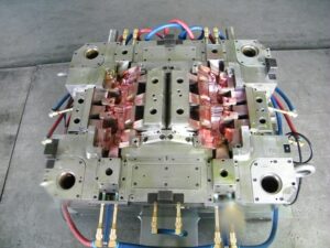
An average ejector sleeve get together plan is given in high precision plastic making mould suppliers china, In this plan, an exceptionally conductive center pin is situated in the back clasp plate and made sure about with an attachment head set screw. The center pin goes through the back brace plate, ejector plate, ejector retainer plate, uphold plate, and center addition to burrow out the ideal part of the shape pit, The ejector peak sleeve is held by the ejector retainer plate and goes through the help plate and center supplement. In the plan of detail A, the finish of the ejector sleeve is coplanar with the highest point of the chief and the nearby rib.

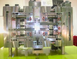
Given the annular math and enormous snapshot of idleness for ejector sleeves, there are normally no issues identified with pressure or clasping. Notwithstanding, the point by point plan of the ejector sleeve is particularly basic since it slides along between a fixed center pin and the fixed center supplement. The pivotal area of the ejector sleeve is administered by the concentric mating of the ejector sleeve with the ejector opening in the center addition. Since the center pin is inner to the sleeve, the divider thickness and concentricity of the trim around the center pin is represented by the resilience stack-up of the ejector opening, ejector sleeve, and center pin. To decrease dimensional varieties in the shaped part, clearances for venting should be limited.
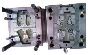
oem mold factory give instances of clearances in the different form plates. The form fashioner ought to guarantee that the center pin has a reasonable freedom through the ejector plate and ejector retainer plate, in any case a slight absence of concentricity between the ejector sleeve and center pin may make the sleeve tie.

This article is from http://www.automoldchina.com/

Ejection System

The ejection system is answerable for eliminating the formed part(s) from the shape after the shape opens. While this may appear to be a basic capacity, the intricacy of the ejection system can shift broadly relying upon the prerequisites of the embellishment application. Numerous issues must be considered including the requirement for various tomahawks of activation, the size and appropriation of the ejection powers, and others to get the automotive molds made in china. Prior to starting the examination and plan of the ejection system, an outline of its capacity is first given.

China industrial injection moulding manufacturers gives a side perspective on a form opening for the resulting ejection of the PC bezel. The ejector gathering (comprising of the ejector plate, ejector retainer plate, return pins, ejector pins, stop pins, and different parts) is housed between the back cinch plate, uphold plate, and rails.

Right now in the embellishment cycle, the shaped part has contracted onto the center side of the form and has been pulled from the form pit as the moving side of the form is withdrawn from the fixed side of the form. In almost no time, the trim machine will push the ejector take out bar against the ejector plate to incite the ejector gathering and strip the formed parts off the center. Right now, be that as it may, a freedom exists between the ejector take out bar and the ejector plate.

Plastic precision injection mould manufacturers china gives a side perspective on the form during the incitation of the discharge system. Preceding discharge, the ejection of the embellishment machine platens isolated the two shape parts to permit freedom for the discharge of the part. The machine at that point drives the ejector take out bar forward to connect with the back surface of the ejector plate. Since the machine can give a power to the take out bar a lot more noteworthy than the power with which the moldings have contracted onto the center, the whole ejector get together is constrained forward. The ejector pins come into contact with the formed part(s) and push the molding(s) off the center.

After the moldings are ejectioned out, the embellishment machine at that point withdraws the ejector take out bar as appeared in oem/odm automatives injection molding design factory. A freedom is then made between the front of the take out pole and the rear of the ejector plate, which permits the ejector get together to be reset to its unique situation for the following trim cycle.

There are a few different ways of resetting the ejector system, which will be talked about later. In any case, one regular strategy for restoring the ejector gathering is to just close the form as appeared in precision molds made in china. The front surface of the return pins will at that point contact the contradicting face of the A plate. The back surface of the return pins will at that point drive the ejector plate, ejector retainer plate, and all the ejector sticks in reverse as the form closes.

The plastic moldings will in general psychologist during cooling and will ordinarily stay on the shape centers upon the kickoff of the form. All things considered, systems are needed to push the parts off the shape during the ejection stage. While this essential capacity is handily perceived, there are a few related plan destinations that ought to be fulfilled in the plan of the ejection system.

This article is from http://www.automoldchina.com

Cooling Line Network

At the point when molds have more than one cooling line, an issue will emerge with regards to how the trim machine administrator will associate the shape to the form temperature regulator. Think about the PC bezel, overlaid with cooling lines as appeared in plastic precision injection mould manufacturers china.

The shape has been furnished with eight cooling lines crossing over the width of the form hole. Confronted with eight cooling line associations, the machine administrator may utilize short hoses to circle the cooling lines as appeared. Such an arrangement has two intensifying issues. To start with, the stream obstruction through the consolidated length of all the cooling lines can be incredibly high, decreasing the coolant stream rates per Eq. .9.16. Second, the form coolant temperature can increment along the length of the cooling circuit at decreased coolant stream rates. Accordingly, a noteworthy temperature differential can emerge from where the coolant enters the shape to where the coolant leaves the form.

Mindful of this issue, numerous if not most decays have coolant manifolds introduced on the trim machine between the shape temperature regulator and the form. The administrator would then be able to utilize longer cooling hoses to separately associate two arrangements of Cooling lines with a short profit circle for the contrary side of the form. Such an equal arrangement is appeared in newest double coler mold parts. This design is very basic since it is basic and gives viable cooling. Notwithstanding, the establishment and expulsion of the form from the machine is muddled by the quantity of lines that must be associated and separated. The high number of hoses and administrator steps additionally improves the probability that the cooling framework might be arrangement mistakenly or fizzle, for example, because of an approximately associated hose.

There is as of now a lot of enthusiasm for the plastics business in lean assembling, which places noteworthy accentuation on decreased cycle intricacy and arrangement times [14-16]. By putting somewhat more in the infusion shape, it is conceivable to decrease the form arrangement time, lessen potential disappointment modes, and improve the form execution. Injection mould manufacturers shows the expansion of two vertical cooling lines interfacing each of the eight flat lines inside the infusion shape; twenty weight plugs have been introduced to hinder the coolant stream at chosen areas. The outcome is that a cooling complex has been planned inward to the form, with the end goal that lone two associations are required. Simultaneously, the cooling consistency is expanded. This inside complex plan has almost no additional expense while conveying both expanded execution and convenience.

Once stopping is viewed as a choice in the steering of cooling lines, a lot more intricate cooling line format become accessible. In the cooling framework plans for the bezel appeared in china standard components for injection mold, the part of the cooling lines situated inside the screen region of the bezel isn’t eliminating any huge warmth. In the event that a two-plate form with a cool sprinter is utilized as appeared in oem/odm automatives injection molding design factory, at that point these cooling lines would cool the sprue and sprinters. For a three-plate or hot sprinter shape, be that as it may, there is no warmth being produced in the focal region of the form cavity. Given that there is no requirement for cooling in the focal point of the form, it is conceivable to course the cooling lines around the outskirts of the part to improve the cooling of the shape hole while lessening oem/odm injection moulding tooling costs and giving a shape that is considerably simpler to work.

This plan gives usability, moderate stream obstruction, and uniform cooling about the whole embellishment.

This article is from http://www.automoldchina.com

Routing the Cooling Line

When the cooling line distance across, profundity, and pitch have been resolved, the cooling lines can be steered through the form. This steering is of basic significance since it not just effects the expense and nature of the moldings, yet additionally restricts the position of other form segments, for example, ejector pins and jolts. By and large, the shape configuration ought to give at any rate a large portion of a cooling distance across between the outside of the cooling line and the outside of some other form part. This plan imperative is given to keep up the basic trustworthiness of the form while additionally limiting cooling spills during mold activity because of consumption. The concealed zone in Fig. 9.8 speaks to the potential areas in the form where cooling lines might be set.

While the concealed zone of Fig. 9.8 speaks to a huge segment of the shape, the arrangement of cooling lines is additionally obliged by possible obstruction with the form hole, hole embeds, center supplements, ejector return pins, direct pins, sprue bushing, and other shape parts. The past examination for the cup/top shape proposed that the cooling framework configuration use: a cooling line distance across of 6.35 mm, a cooling line profundity of 12.7 mm, and a cooling line pitch of 25.4 mm.

The plan actualized precisely to these proposals is appeared in injection mold company china. This underlying plan is infeasible for some reasons. Maybe the most noteworthy inadequacy in the plan is that a significant number of the cooling lines cross basic form highlights, for example, the sprue bushing or the interface between the pit embeds and the shape plates. There are two unique procedures to determine this issue. One methodology is to amplify the depression embed, center supplement, and related form plates to fit all the cooling lines inside the envelope of the center and pit embeds. This choice is exorbitant since it requires update of the shape, acquisition of a bigger form base, and all the more machining. Notwithstanding, such a plan might be financially legitimized given the more fast and uniform cooling.

An elective methodology is to move the cooling lines further from the form depression while keeping up a similar pitch to profundity proportion for the Cooling lines. The subsequent plan is appeared in china industrial injection mold suppliers. This plan requires less Cooling lines, all of which stay away from the crossing point with other shape parts. While this plan gives helpless cooling execution, it is very normal. An essential favorable position is that the entirety of the cooling lines are straight, yet each C0oling line additionally goes through a solitary shape plate also. Accordingly, the C0oling lines can be machined in a solitary arrangement with no requirement for seals or gaskets. Shockingly, the position of the cooling lines a long way from the form pit will lessen the pace of warmth move and require longer process durations. The pace of warmth move is additionally diminished since the c0oling lines are put in another plate, and there will be a warm contact obstruction related with the warmth stream between the two plates [13].

There is a second critical inadequacy in cooling line format of china industrial injection moulding manufacturers, which originates from the utilization of a straight cooling line with a center of huge stature. The wellspring of cooling is the help plate behind the center addition, a long way from the warmth source beginning from the plastic dissolve in the depression. All things considered, critical temperature varieties will create all through the form and shaped part during cooling.

The anticipated temperature disseminations toward the finish of the trim cycle for the cup are given in Fig. 9.11, in which each shape line speaks to a 2°C change in temperature. Because of the generally profound center, an angle of 6°C exists from the base of the center to the head of the center. The temperature angle in pp joint fitting mould will drive differential shrinkage along the hub of the cup just as differential shrinkage through the divider thickness of the embellishment. The explanation is that the temperature at the head of the center isn’t just 6°C more sizzling than the temperature at the base of the center, but on the other hand is generally 6°C more sultry than the temperature at the contradicting surface on the cavity embed. Three choices for redressing the circumstance incorporate utilizing a profoundly conductive center addition, actualizing a confuse or bubbler, or planning a cooling embed. These distinctive cooling plans are next examined.

This article is from http://www.automoldchina.com/

Moulding Parts Design

Below offers a brief view of moulding design process: rib design and boss design in plastic molding service.

Rib Design

Consider the ribbed part configuration appeared at the focal point of Fig. 2.5 comparative with a section having a more noteworthy uniform thickness appeared at left. In this ribbed part plan, the base thickness of the rib is 70% of the divider thickness of the part, H, and the tallness of the rib is multiple times the divider thickness of the part. The two ribs are dispersed at multiple times the divider thickness of the part. Examination of this plan demonstrates that this structure has a firmness proportionate to the part that is 30 % thicker however doesn’t have ribs. Nonetheless, the 30 % thicker part will devour roughly 15% more material and have a 70% longer process duration than the more slender part with ribs. In that capacity, the expansion of ribs can give critical execution and monetary points of interest.

Item planners will in general augment the solidness of the ribs by making the thickness of the rib equivalent to the ostensible divider thickness of the part, H, while likewise limiting the draft edge. Ribs thicker than 70% of the divider thickness will in general draw material away from the focal point of the contrary divider when the rib C0ols. The volumetric shrinkage in this area can make inward voids or sink show up on the part inverse the rib. In non-aesthetic applications that utilization profoundly filled materials with lower shrinkage, the rib thickness can be expanded. Something else, a rib thickness under 70% of the ostensible thickness ought to be utilized in trim applications with unfilled materials [16]. Correspondingly, draft of1° per side is regularly used to encourage discharge of the formed ribs. This measure of draft might be lacking for profound ribs or for parts formed with vigorously filled saps.

Boss Design

Managers of plastic injection moulding services china are regularly used to make sure about different segments along with the utilization of self-stringing screws. Some extraordinary manager plans are given here. The furthest left structure furnishes a manager close to a corner with two ribs and a gusset set at 120°. The inside structure shows a supervisor 0n a rib with two gussets at 90°. The right-most plan shows an unattached supervisor with gusseted ribs that accommodate a raised get together surface. All these manager structures use a chief, rib, and gusset thickness of 70 % times the ostensible divider thickness. Like the rules for rib structure, the divider thickness and draft plot for gussets can be altered considering their tallness and the material being formed.

Planned supervisors in high precision plastic injection mould manufacturers must have the option to withstand the force applied during addition of oneself stringing SCrews just as the possible malleable draw out powers applied during end-use. Simultaneously, in any case, managers ought not be planned with excessively thick areas that may require expanded process duration or mess stylish up. In the plans of Fig. 2.6, n0 draft was used on the supervisors and gussets. These plan highlights are imperative to the basic trustworthiness of the part, yet are little comparative with the size of the whole part. Thusly, utilizing less draft on these highlights can help in expanding the solidness and quality of the embellishment without essentially expanding the discharge powers. In any case, launch of managers can be an issue in infusion shaping, so draft and ejector sleeves can be utilized to aid discharge of tall supervisors that will require enormous discharge powers.

This article is from http://www.automoldchina.com/.