Klarm Mold Offers Coinjection Molds

Co-injection molding is an interaction wherein two materials are consecutively infused into a mold cavity, commonly through a similar entryway in injection moulding service. Since the principal material structures a skin and the subsequent material structures the center of the molded part, it is feasible to utilize co-injection trim to deliver plastic parts with novel stylish or primary properties with possibly lower costs than infusion shaping. Some run of the mill co-injection molding applications include:

■The utilization of a first virgin material having favored restorative properties followed by a subsequent material having diverse underlying properties anC/or reused content, as in the belt of a vehicle guard.

The utilization of a first material followed by a second frothing material to create a restorative part with lower thickness, as in underlying froth applications.

■The utilization of a first material followed by a subsequent liquid, like air or water, to deliver an empty part like an entryway handle.

While this last model (normally known as gas help or water help or liquid help shaping) may not appear to be a co-injection interaction, the embellishment cycle and form plans are adequately like warrant a joint conversation.

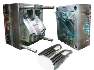
In co-injection molding, two materials are consecutively infused, regularly like the succession gave in oem/odm industrial injection mold factory. As appeared, a first liquefy is mostly infused into the form through a sprue 6 or some other feed framework. After an ideal volume of the primary material 7 has been infused, a second material 8 is infused at a similar area. In the event that the volume of the primary material is too little, the second material may”blow through”the first material. Then again, too enormous an underlying charge of the primary material may leave too little a volume for the infusion of the subsequent material, Since the main material is nearby the form divider, and may have somewhat cemented, the subsequent material will in general move through the center of the principal material.

After the subsequent material has been infused, it is genuinely basic to then infuse a modest quantity of the principal material 9. This last infusion of the primary material serves to cleanse the feed arrangement of any undesired measure of the subsequent material, which may somehow sully the resulting shaping cycle.

It is seen in mold manufacturing factory that the mold center 2 is moving all through the form pit 1 during the infusion of the materials into the mold to in this manner change the divider thickness of the pit 3. This infusion pressure fills in any event two needs. To start with, in froth shaping, the pressure and ensuing extension of the form pit can be utilized to defer and therefore empower the nucleation of gas cells, consequently controlling the dispersion and thickness of the infused froth. Second, in non-foam molding, the pressure of the depression can be utilized to control the pack pressure all through the mold and in this way control the shrinkage attributes of part includes molded of the primary material while infusing the subsequent material. The control of the hole divider thickness can be refined by profiling the uprooting of the embellishment machine’s platen during the filling stage, or then again profiling the clasp weight profile. This article is from http://www.automoldchina.com/

Feed System & Runner

The plan of the feed system is basic to infusion shaping yet is regularly dubious. One basic issue is the ability of an accessible trim machine to fill the shape with a material whose stream attributes are obscure. Then again, there might be vulnerability with regards to the specific liquefy stream rates and weights that are needed to appropriately adjust a family mold or complex multi-gated part / injection molded part.

In questionable circumstances, the form architect ought to determine feed system measurements that are”steel safe,”which implies that the plan should require the expulsion of less shape steel than may eventually be required. Accordingly, the shape architect may wish to adjust the feed system measurements down a couple of standard sizes. Thusly, the shape originator will force a more prominent weight drop and utilize less material than anticipated by the investigation. There is a sensible possibility that the modest feed system may work appropriately. Besides, on the off chance that the feed system requires at least one changes, at that point the”steel safe” plan might be effectively machined with bigger runner sizes to improve the form execution.

Mold manufacturing factory suggests a”steel safe” runner plan if the examination showed an ideal distance across of 4.6 mm for a chilly runner. On the off chance that the feed system examination brought about a runner distance across of 4.6 mm, at that point the shape creator may indicate a measurement of 4.5 mm or even 4 mm for a “steel safe” plan. By correlation, if the form fashioner had gathered together to 5 mm, the plan would have given a lower pressure drop yet expended pointless material all through the shape’s whole lifetime. Moreover, in the event that the disintegrate wanted to lessen the 5 mm breadth, at that point the form would require more broad adjust including pocket processing of the old feed system, the assembling and fitting of a properly measured supplement, welding or potentially the expansion of latches, lastly the arrangement of the new, littler feed system. While this model zeroed in on steel safe plan of cold runners, the steel safe idea is additionally relevant to hot runner plans.

As recently portrayed by oem/odm injection mold factory, the most widely recognized sorts of feed systems are cold runners and hot runners. The two kinds of feed systems have detriments. With cold runners, there is impressive material waste related with the arrangement of the feed system just as the potential for broadened process durations. With hot runners, there is the extra expense and intricacy related with the temperature control systems, just as the potential for temperature varieties and shading change issues.

As an option for high precision mould china in contrast to both cold runner and hot runner designs for injection molding china, the protected runner was planned trying to kill these impediments. The plan design is fundamentally the same as a three-plate shape with a runner segment 15, a cavity segment 16, and center areas 17. The runner format is likewise comparable with a sprue 19 passing on the liquefy through the plate thickness to essential and optional runners 18 that pass on the soften over the splitting plane to a second arrangement of sprues, 22 and 23, which pass on the dissolve down to the shape depressions. Contrasted with a customary three-plate shape, be that as it may, all fragments of the feed system are intentionally intended to have huge distances across. In expansion, the runner segment 15 is made sure about to the depression area 16 and doesn’t open at all during ordinary embellishment.

During the trim cycle, the soften is infused from the spout of the embellishment machine and totally flls the feed system. A skin, 18a and 18b, promptly shapes on the outside of the runners. Be that as it may, the set skin doesn’t completely engender all through the runner, since the warm conductivity of plastic is exceptionally low and each forming cycle passes on warmed polymer dissolve from the trim machine all through the feed system.

Accordingly, the measurement of the liquid center remains almost predictable during the trim cycle. Thusly, the protected runner can be worked as a hot runner, though with no warmers, thermocouples, or temperature regulators. The shading change issue is settled by eliminating the completely hardened feed system with the arrival of runner area 15 from the cavity segment 16. This article is from http://www.automoldchina.com/

the Cavity and Parts Moulding

China precision injection plastic parts factory knows that shut-offs are contact regions between the center addition and the hole embed that different segments of the pit framed between the center and hole embeds. A shut-off should be characterized for every window or opening in the formed part. On the other hand, on the off chance that a section has no windows, similar to the cup, at that point no shut-offs are characterized. The edge of each shut-off is likewise characterized by a splitting line, which ought to be situated in a non-visual territory where an observer line or slight lashing would not lessen the estimation of the shaped part.

For instance, the PC bezel has one enormous opening over the splitting plane for the showcase. A shut-off is essential over the whole region of the opening, there are basically two potential areas for the shut-off’s splitting line, relating to the top and base of the rack that underpins the presentation.

Either area (or even any area in the middle of) would almost certainly be satisfactory with oem/odm automotives mould factory since the whole rack is escaped see.

With the meaning of the splitting plane and all fundamental shut offs, the center addition and the hole embed have been totally isolated. To make the pit and center embeds, the length, width, and stature of the additions must be characterized.

Depression and center supplement measuring rules are portrayed that have been grown so the length and width of the hole and center additions are sufficiently huge to:

(1) encase the pit where the part is framed,

(2) withstand the powers coming about because of the liquefy pressure applied upon the region of the pit,

(3) contain the cooling lines for eliminating heat from the hot polymer dissolve, and

(4) contain different parts, for example, holding screws, ejector pins, and others.

These prerequisites recommend making the center and depression embeds as extensive as could be expected under the circumstances. For littler shaped parts, expanding the measuring the center and pit supplements may have little included expense. Nonetheless, the expense of bigger center and pit additions can get unnecessary with increments in the quantity of cavities or shaped part size.

The stature measurement is regularly dictated by two necessities. To start with, the center and depression addition ought to have enough tallness above and underneath the shaped part to securely pass a cooling line. Cooling line distances across commonly extend from 4.76 mm (3/16″) for littler molds to 15.88 mm (5/8″) for enormous molds. For the most part, enormous supplements with bigger cooling lines will give quicker and more uniform cooling. While cooling line configuration will be later talked about, the base tallness measurement between the shaped part and the top or base surface of the supplement is normally multiple times the distance across of the cooling line to stay away from over the top pressure. The underlying stature measurements for the center and cavity embeds are appeared.

Second, the center and cavity supplement ought to have a tallness that is coordinated with the stature of accessible cavity and center addition retainer plates (the”A”and”B”plates). These plates are usually accessible in %” increases for shape bases planned in English units, and in 10 mm increases in metric units. Accordingly, the supplement statures ought to be chosen up in size to such an extent that the essences of the hole and center additions are flush or marginally raised concerning the”A” and”B”plates on the splitting plane.

It ought to be noticed that the tallness of the center addition as shown isn’t its complete stature but instead the stature measurement from the back surface to the splitting plane. For materials acquisition and cost assessment, the all out tallness of the center addition ought to likewise incorporate the stature of the center over the splitting plane in addition to some wellbeing stock to take into account machining and wrapping up.

This article is from http://www.automoldchina.com/.