China precision injection plastic parts factory knows that shut-offs are contact regions between the center addition and the hole embed that different segments of the pit framed between the center and hole embeds. A shut-off should be characterized for every window or opening in the formed part. On the other hand, on the off chance that a section has no windows, similar to the cup, at that point no shut-offs are characterized. The edge of each shut-off is likewise characterized by a splitting line, which ought to be situated in a non-visual territory where an observer line or slight lashing would not lessen the estimation of the shaped part.
For instance, the PC bezel has one enormous opening over the splitting plane for the showcase. A shut-off is essential over the whole region of the opening, there are basically two potential areas for the shut-off’s splitting line, relating to the top and base of the rack that underpins the presentation.
Either area (or even any area in the middle of) would almost certainly be satisfactory with oem/odm automotives mould factory since the whole rack is escaped see.
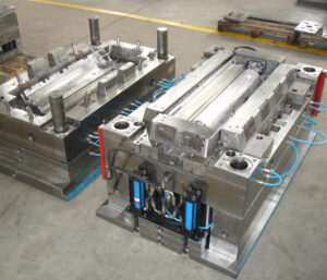
With the meaning of the splitting plane and all fundamental shut offs, the center addition and the hole embed have been totally isolated. To make the pit and center embeds, the length, width, and stature of the additions must be characterized.
Depression and center supplement measuring rules are portrayed that have been grown so the length and width of the hole and center additions are sufficiently huge to:
(1) encase the pit where the part is framed,
(2) withstand the powers coming about because of the liquefy pressure applied upon the region of the pit,
(3) contain the cooling lines for eliminating heat from the hot polymer dissolve, and
(4) contain different parts, for example, holding screws, ejector pins, and others.
These prerequisites recommend making the center and depression embeds as extensive as could be expected under the circumstances. For littler shaped parts, expanding the measuring the center and pit supplements may have little included expense. Nonetheless, the expense of bigger center and pit additions can get unnecessary with increments in the quantity of cavities or shaped part size.
The stature measurement is regularly dictated by two necessities. To start with, the center and depression addition ought to have enough tallness above and underneath the shaped part to securely pass a cooling line. Cooling line distances across commonly extend from 4.76 mm (3/16″) for littler molds to 15.88 mm (5/8″) for enormous molds. For the most part, enormous supplements with bigger cooling lines will give quicker and more uniform cooling. While cooling line configuration will be later talked about, the base tallness measurement between the shaped part and the top or base surface of the supplement is normally multiple times the distance across of the cooling line to stay away from over the top pressure. The underlying stature measurements for the center and cavity embeds are appeared.
Second, the center and cavity supplement ought to have a tallness that is coordinated with the stature of accessible cavity and center addition retainer plates (the”A”and”B”plates). These plates are usually accessible in %” increases for shape bases planned in English units, and in 10 mm increases in metric units. Accordingly, the supplement statures ought to be chosen up in size to such an extent that the essences of the hole and center additions are flush or marginally raised concerning the”A” and”B”plates on the splitting plane.
It ought to be noticed that the tallness of the center addition as shown isn’t its complete stature but instead the stature measurement from the back surface to the splitting plane. For materials acquisition and cost assessment, the all out tallness of the center addition ought to likewise incorporate the stature of the center over the splitting plane in addition to some wellbeing stock to take into account machining and wrapping up.
This article is from http://www.automoldchina.com/.