Minimize the Mold Stress

Injection molds are exposed to elevated levels of weight from the warmed polymer dissolve. At the point when this weight is coordinated across the surfaces of the form cavities, powers result that regularly range from tens to thousands of tons. The foundational layout of the form should be adequately powerful to withstand these powers, yet additionally to do as such while delivering great shaped items.

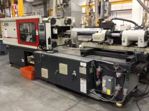
For the chinese injection moulding companies to build up a hearty foundational layout, the shape originator ought to comprehend the connections between the weights, powers, and stresses in an injection form. China high-precision mould suppliers shows the run of the mill stream of stresses through the form, platens, and tie-bars. During embellishment, the dissolve pressure is applied against all surfaces of the form pits. This weight brings about both compressive and shear stresses in the depression embeds, center embeds, and backing plates. This blended condition of pressure is shown by the inclining bolts in china industrial injection mold manufacturers. The embellishment machine’s platens are likewise under a critical condition of adapting to move the powers to the tie bars, which are in strain.

When all is said in done, the form fashioner wishes to give a foundational layout to the shape that will neither break because of exhaustion across many trim cycles, unnecessarily divert under burden, nor won’t be excessively cumbersome or costly. These destinations can be unequivocally expressed as:

■Minimize the pressure,

■Minimize diversion, and

■Minimize cost.

Every one of these targets is next quickly examined after which the itemized examination and plan of molds are introduced.

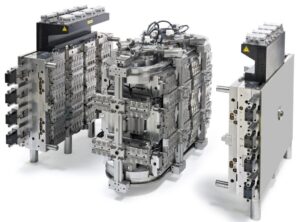
The condition of pressure fluctuates essentially between the moving and the fixed sides of the form. For most forms, the depression embeds are straightforwardly upheld by the top brace plate and the fixed platen. Thusly, the depression embeds are for the most part in a condition of unadulterated pressure so next to no out of plane bowing happens. On the moving side, be that as it may, the pocket needed to house the ejector get together offers no help for the center supplements. Therefore, the center embeds and backing plates should send the heap by means of both compressive and shear stresses, which will in general bring about critical plate bowing.

Mould manufacturers factory plots the anticipated von Mises pressure in a hot sprinter form for the PC bezel when the surfaces of the shape depression are exposed to 150 MPa of dissolve pressure.’ The von Mises pressure, OMises, is a generally utilized basis to foresee disappointment. The cutoff stress is normally dictated by two essential concerns. The main concern is that the pressure ought not be so high in order to plastically misshape the form. At the point when a material is exposed to pressure, it will misshape or strain. For most materials, the measure of disfigurement is relative to the applied pressure. The proportion of pressure to strain is identified with the flexible modulus, E. where ε is the strain that outcomes from an applied pressure, σ. A material with a higher flexible modulus will in general misshape less given an applied pressure.

This article is from http://www.automoldchina.com/

Ejector Layout

The past model inferred that the adequacy of an ejector isn’t just an element of its size yet additionally its area. As a rule, ejectors will be more successful when set close to the areas where the launch powers are created. Further more, the ejectors will be more viable when pushing on inflexible zones of the shaped part. A typical yet inadequate arrangement emerges when ejector pins are consistently disseminated across the shape hole. Such a methodology can offer ascent to the format configuration appeared in china automobile molds manufacturers with an ejector pin found generally a long way from the ribs and side dividers of the embellishment. Since the trim has contracted onto the center, the launch power is being produced by the grinding between the embellishment and the form center at the rib and side divider, By setting the ejector pin a long way from these two staying focuses, a huge second and diversion will be applied before the embellishment is peeled off the center.

The plan can be improved by adding ejector sticks nearer to the rib and side divider as appeared in china injection mold maker. For this situation, three extra pins are added to give . discharge powers near the trim. To maintain a strategic distance from exorbitant pressure in the center supplement because of the pr0vision of the ejector opening, a remittance of in any event one ejector pin measurement should be determined between the outside of the form pit and the outside of the ejector opening. Nonetheless, this ejector pin design may prompt a potential cooling issue since there may not be sufficient freedom to give a C0oling line in the center supplement between the rib and the side divider. In that capacity, the distance across of the ejector pins might be decreased marginally to permit the expansion of a C0oling line whenever wanted.

Another elective format is to give an ejector pin underneath the rib or side divider as appeared in injection moulding services. This plan has the immediate advantage that the erosion power and the launch power are in-line, with the end goal that almost no distortion of the embellishment will 0CCuI. One normal issue emerges because of the slimness of the rib and side divider contrasted with the bigger ejector pin breadth. T0 keep away from minuscule ejectors that may clasp during activity, a strong manager or”ejector pad”may be given on the rib. At the point when the ejector pin is impelled forward, the power is sent from this cushion down the length of the rib and to the encompassing territories of the part. Since the ejector pin pushes straightforwardly on the ejector cushion, n0 draft point is required S0 the ejector cushion breadth can be boosted.

One issue with such a utilization of the ejector cushion, notwithstanding, is the high volumetric shrinkage that can prompt sink on the stylish surface of the part. Thus, a cored out manager catapulted with an ejector sleeve (hence examined) can accommodate more excellent launch yet with a higher shape fabricating cost. The requirement for ejector cushions can likewise be killed using shaped ejector sticks as appeared in china industrial injection mold manufacturers. For this situation, the ejector pin is lined up with one side of the rib or divider, and afterward shaped to push on the top surface of the component. The pin is then shaped and stretched out down at the edge of the component to likewise push on the splitting plane of the embellishment. Contrasted with the past plans, this format takes into account powerful transmission of the discharge powers and minimal ejector pin dispersing with no progressions to the shaped part plan.

This article is from http://www.automoldchina.com

Filler

The consequences of electric cars plastic accessories vacuum forming manufacturers china are plotted with a similar scale for shrinkage concerning plastic injection moulded components china, and show that the straight shrinkage has moved toward that of the fourgated form plan without added cost. Sadly, barely any decays influence the capacities of pack compel profiling to amplify part quality.

Numerous shapeless plastics have shrinkage rates on the request for 0.5 %. Nonetheless, semicrystalline polymers can show altogether higher shrinkage rates. For instance, the particular volume for an acetal (Delrin 500) is plotted in oem/odm 2 shot injection moulding factory. Since acetal is a semi-crystalline polymer, there is a huge change in the particular volume when the polymer advances from a firmly stuffed semi-crystalline strong to an approximately pressed indistinct liquefy. This expansion in the particular volume can offer ascent to critical volumetric shrinkage and high shrinkage rates contrasted with undefined materials. For this equivalent explanation, the shrinkage pace of semi-crystalline plastics is profoundly reliant on the coolant temperature and pace of cooling.

Figure 10.17 demonstrates that the particular volume toward the finish of pressing is 0.77. The material at that point cools and changes to a semi-crystalline strong with a particular volume at room temperature equivalent to 0.69. The overall change in the volumetric shrinkage is 0.90. This compares to a direct shrinkage of 3.5 %. Embellishment applications with such high shrinkage rates will in general be more difficult to control to tight resistances because of their expanded affectability to handle conditions. Besides, colorants can go about as nucleators for semi-crystalline polymers, with the end goal that the shrinkage of hued and flawless variants of exactly the same evaluation may display diverse shrinkage conduct [13]. Best practices for form configuration including reproduction, planning steel safe, and altering the shape and model trim can be utilized to tune the shrinkage of semi-crystalline polymers to acquire tight resistances. At whatever point conceivable, form originators ought to analyze comparative trim applications and evaluate their real shrinkage rates.

To a huge degree, fillers can be utilized to impact the measure of shrinkage that a material shows. The most well-known fillers are mica, glass globule, glass fiber, carbon dark, and elastic. The thickness and coefficient of warm development for these materials are given in injection mold services china.

It tends to be seen from china injection mold maker that, except for elastic (which is normally added as an effect modifier), all the fillers have an exceptionally low coefficient of warm development (on the request of5.10-6 m/m°C) contrasted with that of plastic (on the request for 100. 10-6 m/m°C). Consequently, the expansion of at least one fillers to a perfect tar can be utilized to decrease the polymer’s volumetric shrinkage and in this manner increment the formed part measurements; the adjustment in shrinkage will in general fluctuate relatively with the fllr’s volumetric stacking [14]. The investigation of flled pitches for which the PvT conduct isn’t accessible can be led with the PvT model for the unfilled sap as indicated by the examination model gave in injection mould tooling china.

This article is from http://www.automoldchina.com/

Gate Dimension

After the shear rate, pressure drop, and entryway freeze time have been determined for an underlying plan, the sort and measurements of the door can be changed by injection mold services china to improve the plan. For tasteful and de gating purposes, littler door sizes are wanted. As the past models have appeared, in any case, unreasonable shear rates may direct the utilization of bigger door sizes. These shear rate computations are needy upon an accepted stream rate, and this stream rate won’t be known until after the decay has improved the cycle with the actualized shape. Therefore, the shape planner should accept a sensible stream rate for investigation, select a sort of door that can be augmented, and indicate measurements that are”steel safe.” thusly, the size of the entryways can be promptly expanded to decrease shear rates varying.

Door measurements are may likewise be acclimated to change the weight drops and stream rates at various entryways. Such fine – tuning may assist with adjusting the soften stream between numerous holes, or to modify the stream rates and weave line areas inside a multigated cavity. The degree of the adjusting that can be accomplished through door configuration is incredibly restricted because of the little size of the entryway. To achieve huge changes in stream, china high-precision mould suppliers know that the door measurements must differ by such critical sums that the shear rates and entryway freeze times will shift significantly between entryways, causing unintended outcomes. Thus, it might be wanted to change the components of the sprinters or to utilize a unique stream control innovation for dissolve control.

Entryway measurements are frequently acclimated to improve the dimensional control of moldings by china industrial injection mold manufacturers. At the point when the door hardening time is altogether not exactly the pressing time required by the soften in the hole, at that point inordinate volumetric shrinkage may happen. There are four methodologies that are utilized to decrease the volumetric shrinkage. The most well-known methodology utilized by the disintegrate is to force a high pressing weight before the entryway freezes, with the end goal that the leftover soften pressure in the hole will be assuaged as the liquefy contracts. Lamentably, this methodology can prompt exorbitant glimmering and additionally remaining burdens. Thus, a subsequent regular methodology is to expand the breadth or thickness of the door to build the cementing time and give pressing at more moderate dissolve pressures. A third methodology is to utilize an alternate (regularly molecule filled) material with lower volumetric shrinkage to accomplish the ideal part measurements. A fourth, and frequently kept away from, approach is to adjust the shape to lessen the ostensible thickness of the trim.

The door configuration measure incorporates the choice of the kind of entryway and the cautious determination of the entryway measurements to adjust feel, shear rates, pressure drops, and pressing occasions. The determination of the entryway type will basically be dictated by the past particular of the form type (two-plate, three plate, or hot sprinter), the need to achieve a specific sort of stream in the door or potentially pit, lastly by the longing to give a vigorous and completely programmed shaping cycle. The advancement of door measurements is driven by the tradeoff between little entryway estimates (that accommodate improved style and simplicity of de gating) and enormous entryway measures (that accommodate lower shear rates and weight drops). On the off chance that the detail of the door measurements is dubious, at that point the shape architect ought to use littler entryway measurements since they can be all the more promptly expanded in size whenever required in the wake of trim preliminaries.

This article is from http://www.automoldchina.com.

Fan Gate

The fan gate can be considered as another variation of the edge entryway, in which the width of the fan entryway at the embellishment exceeds the breadth of the runner. One fan entryway configuration is appeared. In this plan of china high-precision mould suppliers, the width of the fan gate has been chosen to stay away from exorbitant shear rates when the liquefy streams into the depression at a high volumetric stream rate. Given the huge width of most fan entryways, the feed framework is ordinarily eliminated by a fueled gate shaper, responding saw, or switch.

One regular utilization of fan gates for the pom moulding parts manufacturers china is to give a direct liquefy stream from the entryway rather than the outspread stream that will result with the previ0us gate plans. A straightforward formed plaque application with a fan entryway is appeared. For this plan to be powerful, two rules must be met. To start with, the fan gate must traverse the width of the trim across which straight low is wanted. Second, the Ilow opposition over the width of the fan gate must be unimportant. Different fan entryway calculations have been created to modify the stream rates into the hole over the width of the fan gate. The plan is normal, and comprises of a basic space between the roundabout segment of the runner and the rectangular segment of the shape hole.

While fan entryways are viable, another option is the blaze gate or film gate. The word”flash” suggests a dissolve course through a dainty area. In like manner, the glimmer entryway comprises of a thick roundabout area that is nearby a slight rectangular segment. During embellishment, the soften will continue from the runner into the thick round area. The slim nearby area will cause the soften stream to slow, cool, and conceivably freeze while the liquefy fills the thick segment. When the dissolve hits the finish of the thick area, the liquefy weight will at that point increment essentially and power the solidified material in the meager segment to stream. Since the stream obstruction along the thick area is little contrasted with the stream opposition over the slim segment, the blaze entryway gives an almost straight dissolve stream to the depression over its width.

The idea of the blaze gate can be stretched out to a barrel shaped math to give a straight dissolve stream without sew lines. In this plan, a strong thick”diaphragm”is used to pass on the liquefy from the sprue to the internal outskirts of the form hole. A more slender entryway segment is then used to guarantee a uniform hole filling and furthermore aid the expulsion of the stomach from the embellishment. Despite the fact that the math of the stomach entryway is barrel shaped, the investigation of the shear A blaze gate can commonly be eliminated by an administrator without the requirement for power helped cutters by consistently flexing the embellishment utilizing the glimmer entryway as a pivot.

Because of the math of the stomach gate, notwithstanding, power apparatuses or a punch press are ordinarily required for de-gating. Both the blaze and the stomach entryways will leave an observer line, so it is wanted to limit the thickness of the gate; average thicknesses are on the request for 0.2 to 0.6 mm, or around 33% the thickness of the formed part. The math and slenderness of these entryways may appear to be to force over the top shear rates and weight drops upon the dissolve. In any case, these gates’ enormous widths will bring about moderately low direct dissolve speeds even at high volumetric stream rates. Thus, these gates can be viably intended to give moderate shear rates and weight drops.

Filling Patterns

Filling patterns can be promptly anticipated utilizing the lay level examination strategy and are valuable to comprehend the conduct of the liquefy in filling the shape, finding doors, recognizing sew line areas, and aiding different parts of mold plan by pom moulding parts manufacturers china. Examination will be performed for a five-sided compartment with a width, length, and tallness of 100 mm, 160 mm, and 60 mm, separately.

Accepting that a two-plate form will be utilized by the mould manufacturers factory, the holder will be gated at the edge of a side divider, To foresee the filling designs, the sides of the compartment are”cut” at the corners and the side dividers collapsed down to make a lay level. The door area is next recognized. The stream will radiate from the entryway, creating a round liquefy front. In that capacity, a curve might be drawn from the entryway speaking to the situation of the soften at a given point in time.

Each bend relates to the area of the liquefy front at an alternate time step; the separation between the curves is equivalent to the straight dissolve speed times the time step. While the liquefy area at the first run through advance is right, the soften will hit the contiguous side divider before the second’s over time step. All things considered, it is important to draw extra curves on these contiguous side dividers mirroring the situation of the soften stream at different time steps. To effectively foresee the stream conduct, the investigation must keep up a similar stream obstruction between the liquefy streaming in the different segments of the form. This can be practiced by making a “phantom”gate and keeping up a similar stream lengths from this “apparition” entryway as from the genuine door.

For each time step, which has been considered by injection molding service china, the length of stream is expanded and a curve of comparing sweep is drawn. Meeting bends comparing to a similar time step are then tended to. The stream is progressed with more ghost doors included varying until the stream all through the whole lay level is made.

High-precision molds made in china shows this liquefy front forecast measure and the subsequent soften front areas for the holder. It is seen that the stream races around the side dividers and will shape a weld line and a gas trap as an afterthought divider inverse the entryway.

This wonder, known as”race – following,” is very regular in shaped parts and can happen when the length of stream around the border of the embellishment is not exactly the length of stream over the center line of the part.

For this situation, race-following happened in light of the fact that the 60 mm profundity of the holder is more than one a large portion of the 100 mm width of the compartment. While the weld line isn’t alluring, a gas trap on a side divider, for example, appeared in china high-precision mould suppliers is particularly risky since it is hard to vent. In that capacity, the caught air will probably combust, causing a consume imprint to show up at this area.

This article is from http://www.automoldchina.com/

Designer Consideration of Mold Specification

It’s known to all injection mould manufacturers in china, the specifications of measurements and tolerances is of basic significance to both the shape originator and infusion decay. Measurements in item plans are commonly determined with supreme tolerances. Here is a case of four unique techniques for determining tolerances. The most widely recognized strategy is the overall resilience, normally indicated in the mark square, which is applied to any measurement without an expressly determined resistance. For this situation, the width counterbalance of 25 mm doesn’t have a predetermined resistance thus would be represented by the overall resilience of土0.2 mm. The tallness counterbalance of 20.0 mm has a predefined reciprocal resistance of士0.1 mm, which is really repetitive with the overall determined resilience of 士0.1 mm for measurements indicated with one decimal spot. On the off chance that the tallness counterbalance was indicated to an alternate resistance, this express particular would supersede the overall resilience.

The opening with a width of 18 mm is indicated with limit measurements, to such an extent that the gap distance across must be between 17.90 mm and 18.00 mm. The two decimals of accuracy don’t mirror any extra exactness 0n the resistance but instead the outright scope of adequate measurements for the gap distance across. At long last, the pole width is determined with a one-sided resistance, implying that the measurement of the pole must be somewhere in the range of 18 and 18.10 mm. The item and form creator would both comprehend from these resilience determinations that the pole is intended to ostensibly fit into the opening with an obstruction fit to such an extent that there is no diametrical leeway between the two.


While item originators of china mould makers will normally think about resilience in supreme terms, plastics disintegrates will in general think about tolerances in relative terms. The explanation is that formed plastics will shrivel as a level of their length, So close supreme resilience will turn out to be more hard to accomplish as the part’s length measurements increment. For example, a run of the mill resilience might be considered as土0.4 % of the ostensible measurement, with the end goal that a 100 mm length would be determined as 100士0.4 mm. A tight resistance might be considered as士0.1 %, with the end goal that a 10 mm breadth might be determined as 10土0.01 mm.


Whoever offering injection moulding services know that the accomplishment of exceptionally close tolerances requires cautious form configuration, process designing, and predictable material properties. Consequently, item creators are urged to determine a solitary general resilience overseeing most measurements alongside just a couple of more tight tolerances 0n explicit measurements that are basic to item. Because a resilience is indicated doesn’t imply that it is attainable. Actually, it isn’t exceptional for item fashioners to over-indicate the resilience on numerous measurements [10]. Shape originators ought to talk about close resistance specification with the item advancement group, and convey that such determinations may require model embellishment to describe the shrinkage conduct, nonuniform profiling of shrinkage rates in various regions of the form, and shape alterations during mold appointing.


Item originators will regularly give particulars on the feel, remembering prerequisites for shading, shading coordinating aCr0ss different segments, and sparkle levels.It is basic for the item configuration to indicate the form surface completion and shape surface, which may add huge expense to the infusion form. Additionally, the shape configuration designer ought to be made mindful of basic tasteful surfaces in which stylish imperfections, (for example, from weave lines, entryway flaw, sink, witness marks, and so on.) ought to be maintained a strategic distance from.


This article is from http://www.automoldchina.com/.

What Standard Moulds Bring?

For china bi-injection mould manufacturers there are numerous advantages for shape structures that depend on the utilization of the standard form bases. These include:


Above all else, the plan of the form base including its many point by point fits and resilience would require broad examination and care in assembling. At the end of the day, most form architects and shape creators would experience issues planning as great a form base at as l0w an expense as a standard item that could be bought off the rack with insignificant hazard and lead times.

Second, the utilization of guidelines accommodates likely interoperability of form bases and shape base parts across trim applications just as various embellishment offices. For instance, a shape creator may wish to give six indistinguishable forms with the goal that two duplicates of each form are operable in Europe, the Americas, and Asia automotive injection mold manufacturers in China. The utilization of a shape base not just backings the form plan concerning a CAD library, yet additionally the arrangement of the substitution segments utilizing the shape base gracefully chain should shape parts become harmed or worn.


Third, the utilization of a standard shape of pom moulding parts manufacturers china base backings for more fast correspondence of the form structure with other industry professionals. For instance, consider the utilization of a form base with a sprue bushing contrasted with a specially craft that strings the trim machine spout straightforwardly into a shape cavity. The utilization of the sprue bushing may build the part tally, however bolsters prepared substitution and standard interfacing to an assortment of trim machines. On the other hand, the straightforwardly strung spout disposes of the sprue out and out thus gives better trim efficiency, however requires more aptitude in planning and activity, There is positively the open door for shape architects, form producers, and decays to beat shape bases utilizing custom form structures without any preparation. These bosses have created noteworthy experience and understanding into their trim applications that rouses and bolsters their hand crafts.


For every one of these reasons, form originators and producers of medical instrument mould made in china in created nations, where work is generally costly contrasted with the shape materials and parts, will regularly utilize standard shape bases. There are numerous providers of form bases who contend with various methodologies including material innovation, quality, lead time, cost, size, broadness of product offering, unit frameworks, territorial appropriation, and others.


Item creators, form originators, shape producers, and decays ought to check what arrangement of providers are to be utilized in a given application.


It ought to be noticed that the expenses of completely acknowledged molds will differ significantly, and not exclusively as a component of structure and quality. The creator has led investigation into shape citing, as knows about examples where completely structured, machined, and completed molds have been bought for not exactly the expense of simply the form base in the United States. These events are frequently the aftereffect of substandard plans, materials, and work rehearses that require broad modify and still perform at imperceptibly satisfactory levels. With further globalization of industry, work rates and material costs will keep on equilibrating so item and form originators may hope to best contend on the development and effectiveness of their structures.


Adherence to principles and great designing practices are fundamental to long haul intensity. The Society of the Plastics Industry (SPI) has given specfication to Class 101, 102, and 103 molds proposed for creation of mutiple 1,000,000 cycles, 500,000 cycles, and 250,000 cycles, separately. A portion of the details are evaluated. For instance, Class 101 and 102 molds are required to have a Brinell Hardness Number (BHN) of 280 while Class 103 shape just require a BHN of 165.


This article is from http://www.automoldchina.com/.