Lid Molding

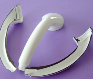
The embellishment of the cover appeared in detail B of high precision plastic injection mould factory presents a completely independent issue identified with the launch of the shaped undercut from the center supplement. As appeared in this detail, the side mass of the shaped top should twist so the lip of the cover can get away from the undermined on the center addition. In the event that the measure of strain brought about by launch is inside the flexible furthest reaches of the material, at that point such undermines can be dependably formed and catapulted from the shape without unique concerns. Indeed, stripper plates are ideal for such launch since they give uniform discharge powers that are almost in _line with the contact power between the embellishment and the center.

The strain, e, brought about by an undercut during launch can be promptly assessed as the measure of avoidance, δ, that the part is needed to go through isolated by the distance, L, across which the diversion is applied, or: ε=δ/L

Index A gives some material properties to different plastics, including the strain to yield. It is seen that most plastics have a strain to yield above 2%, which is a sensible form plan rule. The exemption is vigorously filled materials, which have a lower flexible cutoff and will in general fall flat in a fragile way.

The launch power for a section that is flexibly distorted during discharge can likewise be assessed. To begin with, the pressure in the distorted segment of the part can be determined as the forced strain duplicated by the modulus of the material, E: σ= Ee

This pressure goes about as a loop pressure around the border of the part, like the past examination. The ordinary power is assessed as: Fnormal=σAcontact This power is more noteworthy than the discharge power needed to launch the cup on the contrary side of the shape. Lopsided launch powers can prompt lopsided wear in the form because of bowing minutes applied across the ejector or potentially stripper plates that cause nonuniform weight on guide pins and bushings.

To limit this wear, the thickness of the stripper plate and the size of the guide bushings can be expanded. Furthermore, the stripper plate should be impelled at two areas that are in-accordance with the hub of the depressions rather than one essential issue as shown in high precision molds china.

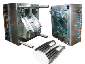
The term”core pull” or”side action”generally alludes to a gadget that withdraws a center toward a path that isn’t resemble to the initial course of the shape. Center pulls permit the embellishment of parts with moderately enormous, complex undermines that may some way or another not be monetarily plausible to deliver.

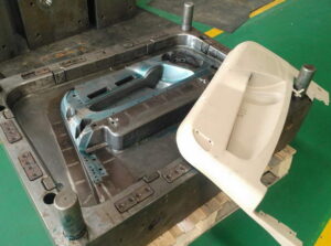
For instance, the item plan of the bezel may require the trim of sidelong managers and a window as appeared in injection moulder services. To form these highlights, an additional shape embed is needed to give the steel around these highlights. This shape embed should be taken out before the launch of the form and the activation of the discharge framework.

This article is from http://www.automoldchina.com/

Minimize the cost

The discharge framework is generally situated on the moving side of the form alongside the shape centers. Since ejector pins and different segments contact the trim, they leave observer marks on the adjoining surfaces, which can

■reduce the visual nature of the trim’s surface,

■interfere with mating gathering surfaces, and

■reduce quality in auxiliary applications.

Thusly, ejector pins and different parts ought to be found and intended to minimally affect the trim’s surfaces.

The most widely recognized methodology is to find ejector pins on non-visible surfaces and in low pressure regions of the embellishment. On the other hand, bigger parts, for example, sleeves, slides, lifters, and stripper plates might be deliberately utilized by high precision molds china with the end goal that their observer lines correspond with highlights of the trim. These deliberately planned segments can leave no evident observer line while giving successful launch across enormous territories of the part surface.

A few applications require one side of the trim to be totally liberated from all observer marks. In these applications, one technique in form configuration is to find the whole framework on the fixed side of the shape alongside the feed framework. This “opposite discharge” plan permits the outside of the moldings confronting the moving side of the shape to be totally liberated from witness stamps because of both the feed framework and the launch framework. This plan will be examined in more detail.

The expense of the discharge framework can be either an irrelevant or a huge part of the all out shape cost. The least complex molds utilize a tradable arrangement of ejector sticks, each with a similar measurement and length; such a plan follows plan for assembling and gathering rules [1] for part compatibility to limit the shape get together time and support necessities. Notwithstanding, most shape utilize various distinctive ejector pins with differing measurement, segment, and length. While the expense of extra expense of the pins is little contrasted with the expense of the mold, the mold designer of oem/odm industrial mold factory and form producer ought to make certain to key and name every ejector pin so they can be promptly kept up by the decay.

The expense of the ejector framework can increment significantly with the utilization of slides, lifters, and other launch sub gatherings. Once more, the objective of the shape planner is to give a basic, savvy, and solid plan that fulfills the recently depicted targets. The shape architect ought not simply think about the underlying plan and tooling costs, however the operational, support, and disappointment costs too.

The ejector framework configuration of china automobile molds factory is resolved first by the necessary format of the shape’s splitting surfaces, and accordingly by the definite plan of the different parts needed to discharge the molding(s). The accompanying plan measure accepts that the formed part of china custom mold components has been appropriately planned with a base number of under-cuts, and so on Something else, the shape fashioner ought to return to the part configuration to disentangle the form’s discharge framework plan. This article is from http://www.automoldchina.com/

Machining Time Cost

The cavity volume machining time of oem/odm automotives injection mold factory is a component of the volume of material to be taken out and the material evacuation rate. To give a surmised however traditionalist gauge, the supposition that is made that the evacuation volume is equivalent to the whole volume of the center and hole embeds. This may appear to be an excessively traditionalist gauge, yet in truth a significant part of the volume must be eliminated around the outside of the center supplement and within the cavity embed.

The material evacuation rate by mould manufacture factory is an element of the cycles that are utilized, the completion and resistances required, just as the properties of the shape center and hole embed materials. To rearrange the examination, a mathematical unpredictability factor will later be utilized to catch the impact of various machining cycles and resistances expected to create the necessary hole subtleties. Accordingly, the volume machining time catches just an opportunity to require the material evacuation as follows.

where Rmachining is the volumetric shape material machining rate estimated in cubic meters every hour. Machining information for various materials are given by china industrial injection moulding manufacturers, however application-explicit material evacuation rates can be subbed if the profundity of cut, speed, and feed rates are known.

The depression region machining time, taviy zone, gauges the time needed to machine all the hole surfaces, and is comparatively assessed as follows where Apart surfae is the all out surface territory of the part estimated in square meters and Rmaterial zone is the zone form material expulsion rate estimated in square meters every hour. Current 3D PC supported plan frameworks can give a precise proportion of the part’s surface zone and volume.

The hole unpredictability factor, fcavity. intricacy; changes the cavity machining time to represent the plan and assembling of the bunch of highlights that will form the shape depression. A portion of the exercises that the intricacy factor represents include:

■Decomposition of the form cavity into different machining undertakings;

■Generation of machining assignments and NC programs, including cathodes for electrical release machining;

■Execution of machining assignments, including numerous machine arrangements, electrical release machining, processing, and so forth;

■Inspection and revise to acquire all the predetermined calculation.

Past exploration [5, 23] has discovered that the multifaceted nature of the depressions is identified with the all out number of measurements and additionally includes determined in the plan of the part to be formed. Tragically, these previous cost assessment approaches are tedious and subordinate upon the abstract supposition with respect to what comprises a measurement or highlight. Accordingly, this cost examination utilizes a multifaceted nature factor that depends on the proportion of the normal volume of the part (the surface territory, Apart _surface, times the divider thickness, hwll) contrasted with the genuine volume of the part, Veart”

This multifaceted nature factor increments with the option of highlights, since each additional component, (for example, a rib, chief, or window) expands the surface region of the part without causing a noteworthy increment in the genuine part volume. To show various degrees of intricacy, Table 3.8 gives the determined multifaceted nature elements to part structures of shifting unpredictability.

The machining factor, fmachining, represents the inconsistency in the material expulsion rates for different kind of machining. The volumetric evacuation rates gave in Appendix B expect a carbide, two fluted, 19.05 mm (%4 inch) distance across end factory with a profundity of cut of 3.2 mm (0.125 inch); the surface region expulsion rate accept a carbide, four fluted, 6.35 mm (%4 inch) width end plant working at a large portion of the ostensible feed rate suggested for the different materials. Since the hole and center supplements are normally delivered with an assortment of machining tasks, the general machining factor for a given application is the weighted normal of every one of the machining factors gave in Table 3.9 in relation to its utilization.

The machining proficiency factor, fmmachining_ eficiency, represents the division of time that work and machine time are spent on non machining exercises. In principle, the proficiency of a completely computerized mathematical control machining cell will move toward 100 %. In actuality, the effectiveness infrequently surpasses half. The explanation is that a lot of time is needed to build up the succession of machine activities, obtain and check cutting apparatuses, perform arrangements, confirm cutting ways, make terminals, work EDM, and different errands. Thusly, a machining effectiveness pace of 25% is suggested for cost assessment reasons.

This article is from http://www.automoldchina.com.