Stack Mold

At the point when the plastic liquefy is injected into the mold hole at high weight by china injection mould maker, huge clip power is needed to keep the mold shut so the dissolve doesn’t get away from the mold cavity. Since the cinch power is relative to the extended territory of the mold cavities, the brace power increments relatively with the number of shape cavities over the splitting plane. In any case, on the off chance that the pits are”stacked” one on head of another, at that point the clip power used to close one lot of cavities can likewise be utilized to close any arrangements of pits that are in the stack.

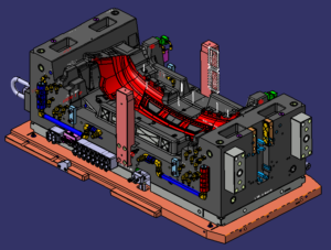
One such stack mold configuration from china precision molds manufacturers, which was intended to shape two vinyl records with the clasp power and process duration typically used to mold one vinyl record. In this plan, two arrangements of stampers are mounted between an internal plate, 12, and two external plates, 14 and 16; the inward plate, 12, is guided by course, 20. The dissolve streams from the spout, 54, of the embellishment machine through broadened sprue, 40, to two arrangements of holes where the records are framed. After the plastic sets, the dissolve shut-off pole, 65, is incited to seal the sprue bay, 51, with the shut-off, 66. This activity additionally associates the sprue, 40, to the chute, 64, to such an extent that the sprue might be taken from the moldings with initation of the sprue take out bar, 75. The shaped records are then catapulted subsequent to withdrawing the sprue take out pole and opening the mold.

There are two in-sufficiency in the mold plan. To begin with, the stack shape requires the arrangement of a sprue, which is scrap. Second, the soften stream to the two holes isn’t adjusted, because of the extra length of the sprue to one side pit. Both these defliciencies are settled in present day stack mold plans that use hot sprinter frameworks.

In this plan of plastic injection molding services china, a focal moving plate, 56, houses two arrangements of depressions, 60, on contradicting separating planes, 62 and 64. A hot complex, 65, conveys the polymer soften to the pits through the sprinter, 70, and ensuing drops. The plan utilizes tw0 single hub valve entryways to convey the liquefy from the trim machine spout, 17, over the splitting plane, 62, and to the complex, 65. During filling and pressing phases of the trim cycle, the actuators, 50 and 54, withdraw the valve pins, 24, to convey the liquefy from the n0zzle to the complex. Something else, the valve pins seal the feed framework during the plastication, Cooling, and mold reset stages.

While the stack shape configuration expands the stack stature and intricacy of the mold, it empowers the embellishment of two arrangements of pits with a similar process duration and clasp power as a solitary arrangement of cavities. Besides, the stream to the two arrangements of holes is totally ba speared and there is no material waste related with the hot sprinter feed framework. Given the huge part cost decreases managed by this sort of stack mold configuration, stack molds are now very normal with two, three, and four degrees of depressions. Unmistakably, the stack shape configuration requires the cautious adjusting of potential preparing cost reserve funds with issues identified with speculation, upkeep, shading change, stack stature, and injection volume by oem injection mold factory.

This article is from http://www.automoldchina.com/.

Feed System Pressure

When the layout and lengths of the feed system have been resolved, the widths of each bit of the feed system ought to be resolved by china precision molds factory.

The progression of polymer soften through the feed system is in the laminar stream system. For china precision molds manufacturers to confirm laminar stream, the Reynolds number, Re, ought to be under 2300. Where is the volumetric stream rate (regularly on the request for 50,10 6 m3/s), .

Pmelt is the thickness (regularly on the request for 1000 kg/m}), met is the clear consistency (commonly on the request for 100 to 1000 Pa-s), and D is the sprinter measurement (ordinarily on the request for 0.01 m). Subbing average qualities for the factors in Eq.6.2 demonstrates that the Reynold’s number is on the request for 0.1. In that capacity, the stream system is a long way from violent, inertial impacts are immaterial, and the weight drop, AP, can be assessed utilizing the well-known Hagen Poiseuille condition. Where L and R are the length and span of a segment of the sprinter. To give a precise gauge of the weight drop utilizing the Newtonian model, the clear consistency ought to be assessed for the polymer soften at a proper shear rate.

For a force law liquid, the weight drop can be assessed straightforwardly without figuring of the shear rate.

In the model of oem/odm injection mold factory, The investigation accept that ABS is formed with a volumetric stream rate at the gulf of 125 cc/s. To abstain from figuring the shear rate in each part of the sprinter, the force law model is utilized with k equivalent to 17 ,000 Pas/and n equivalent to 0.35.

The drag of the hot sprue bushing is 90 mm long and has a range of 6 mm. The volumetric stream rate through the hot sprue bushing is 125 cc/s, so the weight drop through the sprue.

After the hot sprue bushing, the liquefy branches into two stream streams. Since the multigated PC bezel is almost symmetric, the stream rate through every leg of the hot sprinter system is thought to be half of the delta stream rate, or 62.5 cc/s. Every leg of the complex is 1 18 mm long with a sweep of 5 mm, so the weight drop through the complex.

To ascertain the weight drop through the spout, the most exact gauge might be given by examining each fragment of the tightened bore. Given this specific spout bore math, be that as it may, a sensible gauge might be gotten by demonstrating the tightened bore as a consistent segment with a sweep of 3.5 mm and a length of 108 mm. The weight drop is then Once the weight drop through the feed system is investigated, it is conceivable to modify the feed system configuration to improve the presentation. Different emphases of plan and investigation might be led to get a plan that gives a low weight drop while expending almost no material. Multivariate enhancement is a mathematical method that could be utilized to at the same time limit the weight drop while limiting the sprinter volume. Nonetheless, this methodology expects time to actualize and approve while smothering the subtleties of the examination from the fashioner.

This article is from http://www.automoldchina.com/.

Mold in Natural Law

Newton’s law of consistency expresses that the shear pressure, T, between equal layers of stream is corresponding to the shear rate. where the coefficient μ is the clear thickness and is expected consistent for “Newtonian” liquids.

Plastic injection molding services china analyzes the Newtonian model against the non-Newtonian conduct gave by the Cross-WLF model for a medium consistency PC at 280°C. As recently expressed, the polymer soften is known to be non-Newtonian. Consequently, the Newtonian model gives a careful gauge to the consistency just at a shear pace of 7000 1/s. The Newtonian model overestimates the thickness at higher shear rates and thinks little of the consistency at lower shear rates. All things being equal, the Newtonian model is the most straightforward and can give sensible designing appraisals when a delegate shear rate is utilized. Note that china high precision injection molding machine utilizing the Cross model’s Zero shear thickness, 97o, as the clear consistency would bring about a critical overestimation of trim shear stresses and weights since it disregards the shear diminishing conduct close to the pit dividers where most of the stream conductance is produced.

Newton’s law of consistency expected that the thickness isn’t a component of shear rate. At the point when a material doesn’t comply with this law, it is supposed to be non-Newtonian. One of the easiest and most regular non Newtonian models is the force law model, which expresses that the consistency is an exponential capacity of the shear rate. shere k is a consistency list illustrative of the estimation of thickness assessed at a shear pace of one complementary second and n is the force law record.

Figure 5.7 analyzes the force law model against the non Newtonian conduct gave by the Cross-WLF model for a medium consistency PC at 280°C. It is seen that the force law model gives superb evaluations of the consistency at higher shear rates however overestimates the thickness at lower shear rates. Therefore, it ought normal that the force law model will give more precise evaluations than the Newtonian model yet overestimate the weight drop contrasted with the Cross-WLF model, since it over-predicts the consistency at lower shear rates.

It ought to be noticed that a few gums, for example, a few evaluations of polypropylene, progress to a force law system at low shear rates. For these kinds of materials, there is no obvious New tonian level and the force law model can be required to give awesome assessments. For different materials showing a huge Newtonian level, for example, the polycarbonate just examined, the force law model can intentionally fit to a littler shear rate system important to give more exact outcomes.

For stream of a force law liquid, the speed profile through the thickness is an element of the force law file, n. The volumetric stream rate is the basic of the speed over the thickness times the width, W. It ought to be noticed by chinese mold component machining manufacturers that a force law list equivalent to one returns the force law model to the Newtonian model. As the force law list diminishes, the consistency displays expanded shear diminishing with the end goal that the polymer liquefy streams quicker close to the side divider. As the force law record approaches zero, a fitting stream creates in which the liquefy speed is practically consistent through the thickness. These practices are graphically portrayed during china mould make services. Note that that the liquefy speed at the inside line diminishes to keep up a consistent volumetric stream rate as the force law file diminishes.

With the force law model, the shear rate at the divider isn’t needed to assess the weight drop, however it might be valuable to ascertain to dodge over the top shear rates or check the thickness of the liquefy. It tends to be determined from either the normal straight stream velcity or the volumetric stream rate.

This article is from http://www.automoldchina.com

Machining Time Cost

The cavity volume machining time of oem/odm automotives injection mold factory is a component of the volume of material to be taken out and the material evacuation rate. To give a surmised however traditionalist gauge, the supposition that is made that the evacuation volume is equivalent to the whole volume of the center and hole embeds. This may appear to be an excessively traditionalist gauge, yet in truth a significant part of the volume must be eliminated around the outside of the center supplement and within the cavity embed.

The material evacuation rate by mould manufacture factory is an element of the cycles that are utilized, the completion and resistances required, just as the properties of the shape center and hole embed materials. To rearrange the examination, a mathematical unpredictability factor will later be utilized to catch the impact of various machining cycles and resistances expected to create the necessary hole subtleties. Accordingly, the volume machining time catches just an opportunity to require the material evacuation as follows.

where Rmachining is the volumetric shape material machining rate estimated in cubic meters every hour. Machining information for various materials are given by china industrial injection moulding manufacturers, however application-explicit material evacuation rates can be subbed if the profundity of cut, speed, and feed rates are known.

The depression region machining time, taviy zone, gauges the time needed to machine all the hole surfaces, and is comparatively assessed as follows where Apart surfae is the all out surface territory of the part estimated in square meters and Rmaterial zone is the zone form material expulsion rate estimated in square meters every hour. Current 3D PC supported plan frameworks can give a precise proportion of the part’s surface zone and volume.

The hole unpredictability factor, fcavity. intricacy; changes the cavity machining time to represent the plan and assembling of the bunch of highlights that will form the shape depression. A portion of the exercises that the intricacy factor represents include:

■Decomposition of the form cavity into different machining undertakings;

■Generation of machining assignments and NC programs, including cathodes for electrical release machining;

■Execution of machining assignments, including numerous machine arrangements, electrical release machining, processing, and so forth;

■Inspection and revise to acquire all the predetermined calculation.

Past exploration [5, 23] has discovered that the multifaceted nature of the depressions is identified with the all out number of measurements and additionally includes determined in the plan of the part to be formed. Tragically, these previous cost assessment approaches are tedious and subordinate upon the abstract supposition with respect to what comprises a measurement or highlight. Accordingly, this cost examination utilizes a multifaceted nature factor that depends on the proportion of the normal volume of the part (the surface territory, Apart _surface, times the divider thickness, hwll) contrasted with the genuine volume of the part, Veart”

This multifaceted nature factor increments with the option of highlights, since each additional component, (for example, a rib, chief, or window) expands the surface region of the part without causing a noteworthy increment in the genuine part volume. To show various degrees of intricacy, Table 3.8 gives the determined multifaceted nature elements to part structures of shifting unpredictability.

The machining factor, fmachining, represents the inconsistency in the material expulsion rates for different kind of machining. The volumetric evacuation rates gave in Appendix B expect a carbide, two fluted, 19.05 mm (%4 inch) distance across end factory with a profundity of cut of 3.2 mm (0.125 inch); the surface region expulsion rate accept a carbide, four fluted, 6.35 mm (%4 inch) width end plant working at a large portion of the ostensible feed rate suggested for the different materials. Since the hole and center supplements are normally delivered with an assortment of machining tasks, the general machining factor for a given application is the weighted normal of every one of the machining factors gave in Table 3.9 in relation to its utilization.

The machining proficiency factor, fmmachining_ eficiency, represents the division of time that work and machine time are spent on non machining exercises. In principle, the proficiency of a completely computerized mathematical control machining cell will move toward 100 %. In actuality, the effectiveness infrequently surpasses half. The explanation is that a lot of time is needed to build up the succession of machine activities, obtain and check cutting apparatuses, perform arrangements, confirm cutting ways, make terminals, work EDM, and different errands. Thusly, a machining effectiveness pace of 25% is suggested for cost assessment reasons.

This article is from http://www.automoldchina.com.