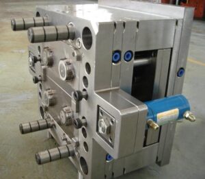
Cooling Line Depth Choosing

In choosing the last cooling line breadth, the mold creator from oem/odm medical mold design factory ought to consider the manufacturability of the cooling lines and the decay’s norms with respect to cooling plugs, connecting peaks, and hoses. High precision molds made in china gives a few details to commonplace cooling plugs gave by a form segment provider (DME). As seen in the table, the business plugs range from 4.76 to 15.9 mm. The form originator should choose a cooling line distance across that fulfills the above examination and is a standard size.

It ought to be noticed that the above examination is generally fitting for water as the coolant. Ethylene glycol and oil are not as normal by and by because of natural and cost concerns. These non-water coolants are additionally considerably more gooey than water, with the end goal that violent stream isn’t probably going to be accomplished. For laminar, thick stream, the weight drop can be assessed utilizing the recently created Hagen-Poiseuille law with the coolant properties of products made by injection moulding china:

The form fashioner should then choose a suitable cooling measurement to guarantee that the greatest weight drop over the cooling lines doesn’t surpass the ability of the coolant temperature regulator.

After the cooling line width has been resolved, the profundity of the cooling lines must be chosen. From an auxiliary perspective, it is attractive to put the cooling lines a long way from the outside of the form pit. Profound arrangement maintains a strategic distance from the pressure fixations related with the evacuation of material near the surface. For reference, Fig. 9.4 plots the pressure forms for shape plans with cooling line profundities, Hime; equivalent to one cooling line breadth at left and four cooling line measurements at right. It is seen that there are pressure fixations around the cooling line, and the greatness of the pressure, σ, increments essentially as the coling line moves toward the form divider, Stress focus factors have been very much dissected for an assortment of materials, calculations, and burden conditions [10]. For a consistently stacked plate with a gap, the base pressure fixation factor is ordinarily somewhere in the range of 2 and 3 [11]. In any event, when the C00ling lines are set a ways off of four breadths, a pressure focus factor of 2.6 is watched. On the off chance that a shape embed is made of P20, which has a perseverance worry (to maintain a strategic distance from weakness) of 456 MPa. At that point the form must be intended for a most extreme dissolve weight of:

Luckily, this dissolve pressure is about equivalent to the greatest infusion pressure for most trim machines, and is probably not going to be completely communicated to the form hole. The pressure fixation related with cooling lines is huge, and this imperative requires the C0oling line to be put far away from the shape surface in trim applications with high liquefy pressures. In any event, when the cooling lines are set a long way from the hole surface, the pressure focuses still conceivably limit the dissolve pressures with which the shape might be worked. As another model, consider the plan of an aluminum shape with a weakness limit pressure equivalent to 166 MPa. On the off chance that the cooling line profundity is equivalent to one distance across, at that point the pressure focus factor is 3.3, which would permit a most extreme soften weight of only 50 MPa.

This investigation doesn’t forestall the disintegrate from working at higher liquefy pressures, yet just demonstrates that the shape will probably not work for a long existence without creating Cracks radiating from the cooling lines. Stress fixations in molds are talked about in more detail in china mould manufacturing. While the auxiliary contemplations propose that cooling lines ought to be put a long way from the shape surface, the pace of warmth move is augmented by putting the cooling lines as near the surface as could reasonably be expected. The warmth conduction condition expresses that the warm obstruction is direct with the separation between the cooling line and the form surface.

This article is from http://www.automoldchina.com
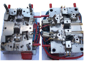
What Influences Mold Development Process

For injection mould supplier china, mold quoting, mold design, and mold making bolster this bigger item development process. Solicitations for mold or potentially part cost cites are typically made towards the finish of the idea configuration stage or close to the start of the definite plan stage. It is to some degree abnormal for the decay or the mold creator to be given completely point by point plans right now. One explanation, a significant part of the mold configuration could have been per-molded simultaneously with a less evolved item structure, and Another Reason, the mold building procedure may propose huge changes in the plan identified with manufacture ability or part execution.


The mold improvement process of china precision mould manufactory regularly starts with a starter structure that is deficient in detail and would bring about an unacceptable item whenever utilized straightforwardly. The basic part plan data required to start the mold idea configuration incorporates the part size, divider thickness, and anticipated creation amount. Given only this data, the mold architect can start to create beginning mold mold, quotes, and item plan enhancements. To quicken the item development process, mold configuration can be per-molded simultaneously with the obtainment and customization of the mold segments.


For better or for more awful, mold making and charging happens close to the furthest limit of the item development process. Consequently, there can be critical weight on mold providers and decays to give great moldings at the earliest opportunity. This undertaking can be amazingly testing given potential errors made before in the item configuration process. In that capacity, mold fashioners might be required to overhaul and change segments of the mold and work intimately with disintegrates to qualify the mold for creation.


There are numerous necessities of an infusion molded part that should be considered during the mold plan of plastic injection tooling china. The structure documentation talked about in this area is to a great extent propelled for two reasons. To begin with, point by point and accessible documentation will improve the plan and lessen the expense of the mold building. Second, ISO and other administrative offices regularly require mold documentation and endorsement of item advancement.

In like manner, the plastic item originator and mold planner ought not think about these worksheets as static pages, but instead as living records that are connected to structure choices and dynamic procedures with steering from and to the related associates for data and endorsement.


The mold configuration specialist of injection mold makers china ought to comprehend the general application and improvement plan. The mold architect should know the proper specialized contact for questions identified with the part plan and its necessities. In a perfect world, this contact ought to comprehend the basic prerequisites of the mold part or have the option to allude the mold planner to other, more educated individuals. On the other hand, the mold creator may contact the inward venture or applications chief liable for supporting the client So as to maintain a strategic distance from persistently reaching the client viewing what might be considered as conceivably insignificant issues. The mold planner ought to likewise know the specialized contact and undertaking administrator at the decay to check molding inclinations, machine particulars, and task coordination. There are a few basic achievements that ought to be followed, including the dates for venture inception, machined holes, mold assessment, molding preliminaries, first article investigation/endorsement, and volume creation. These dates are much of the time haggled since they are identified with specialized feasibility, advertise achievement, and furthermore installment terms.

This article is from http://www.automoldchina.com/

Mold External Look

It’s critical for china plastic mould makers to have the mold clear and right external look before any quotation or production. An isometric perspective on a two-plate form is given in Fig. 1.4. From this view, it is seen that a form is built of various plates shot along with attachment head top screws. These plates regularly incorporate the top brace plate, the cavity embed retainer plate or”A”plate, the center supplement retainer plate or”B”plate, a help plate, and a back clip plate or ejector lodging. Some form parts are alluded to with numerous names. For example, the”A” plate is here and there alluded to as the pit embed retainer plate, since this plate holds the depression embeds. As another model, the ejector lodging is additionally here and there alluded to as the back clip plate, since it clasps to the moving platen situated towards the back of the embellishment machine. In some form structures, the ejector lodging is supplanted with a detachable back clasp plate of uniform thickness and two equal ejector “rails”that supplant the side dividers of the integral”U”- molded ejector lodging. This elective back brace plate configuration requires more parts and form making steps, however can give material cost reserve funds just as shape plan adaptability. Also this should be judged if fit for the chinese injection molding machines.


The form delineated in Fig. 1 .4 is alluded to as a”two plate form” since it utilizes just two plates to contain the polymer soften. Form plans may fluctuate altogether while playing out similar capacities. For instance, some form structures incorporate the”B” plate and the help plate into one extra-thick plate, while other shape plans may coordinate the”A”plate and the top clip plate. As recently referenced, some form plans may separate the ejector lodging, which has a”U”- molded profile to house the launch instrument and clipping openings, into a back clasp plate and tall rails (otherwise called risers). The utilization of a coordinated ejector lodging as appeared in Fig.1.4 accommodates a minimal shape structure, while the utilization of independent back clip plate and rails accommodates more noteworthy plan adaptability. High precision plastic making mould china need to get the clear detailed external view carefully so as to arrange the production.


To hold the form in the injection shaping machine, toe cinches are embedded in spaces adjoining the top and back brace plates and in this manner dashed to the fixed and moving platens of the embellishment machine. A finding ring, typically found at the focal point of the form, intently mates with an opening in the embellishment machine’s fixed platen to adjust the channel of the shape to the trim machine’s spout.


The opening in the trim machine’s fixed platen can be seen in Fig. 1.1 around the embellishment machine’s spout. The utilization of the finding ring is important for at any rate two reasons. To begin with, the channel of the dissolve to the shape at the form’s sprue bushing must mate with the outlet of the liquefy from the spout of the trim machine. Second, the ejector knockout bar(s) incited from behind the moving,platen of the trim machine must mate with the ejector arrangement of the shape.


The oem/odm largest plastic injection molding companies in China have its own ability that embellishment machine and shape providers have created standard finding ring particulars to encourage form to-machine similarity, with the most well-known finding ring width being 100 mm (4 in). At the point when the trim machine’s moving platen is incited, all plates connected to the back clasp plates will be correspondingly impelled and cause the form to isolate at the splitting plane. At the point when the form is shut, control pins and bushings are utilized to intently find the “An” and the “B”plates on isolated sides of the splitting plane, which is critical to the essential shape capacity of containing the soften. Ill-advised structure or development of the form segments may cause misalignment of the”A” and”B”plates, low quality of the shaped parts, and quickened wear of the injection shape.

This article is from http://www.automoldchina.com/.